
Sensor-less operation and detection of CCM and DCM operation modes in synchronous switching power converters

a technology of synchronous switching power converters and operation modes, applied in the direction of automatic control, process and machine control, instruments, etc., can solve the problems of additional power losses of sensing circuitries, speed and power loss of sensing circuitry, noise effect near zero crossing point, etc., to eliminate or reduce challenges, eliminate or reduce challenges and problems associated

Active Publication Date: 2014-06-03
UNIVERSITY OF ALABAMA
View PDF12 Cites 4 Cited by
  • Summary
  • Abstract
  • Description
  • Claims
  • Application Information

AI Technical Summary

Benefits of technology

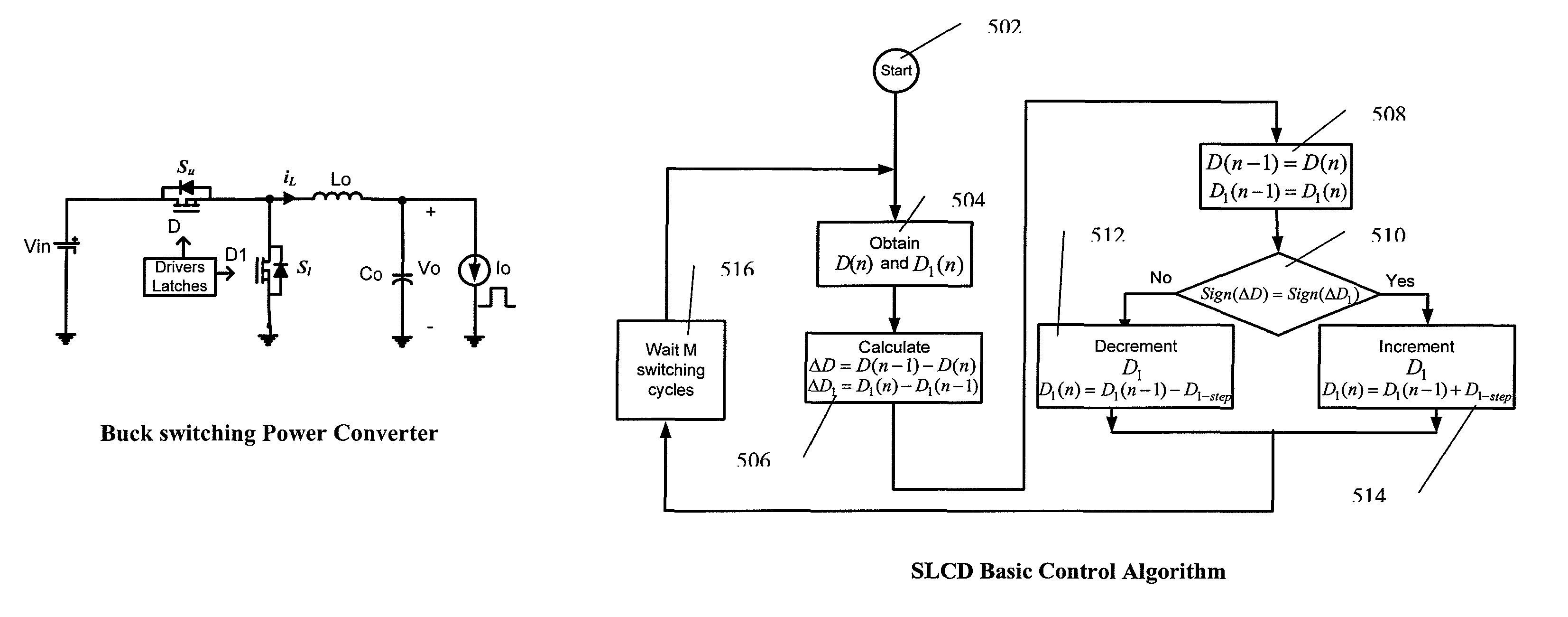
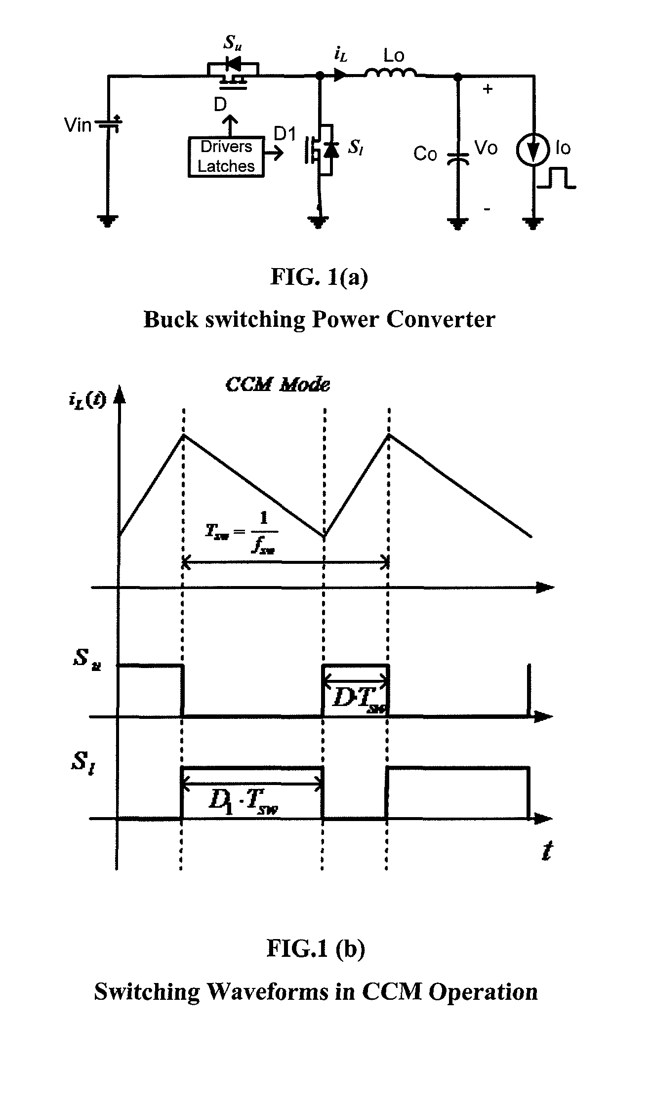
[0009]Generally, described herein are embodiments of control schemes for sensor-less operation and detection of CCM and DCM in a switching power converter. In one aspect, embodiments of a controller are described that utilize dual control loops and do not require sensing the inductor current or any current in the converter which eliminates or reduces the challenges and problems associated with current sensing. Advantages of embodiments of methods described herein become more significant when used in ultra high switching frequency converters (as explained in references [8, 9] listed on page 12) since embodiments of the controller result in eliminating the need for high speed low-noise current sensing circuitries, when used in on-chip integrated power converters where sensing accuracy may be a more significant issue compared to on-board power converters, and in power converters With paralleled modules since embodiments of the controller eliminate sensing circuitries in each of the modules.
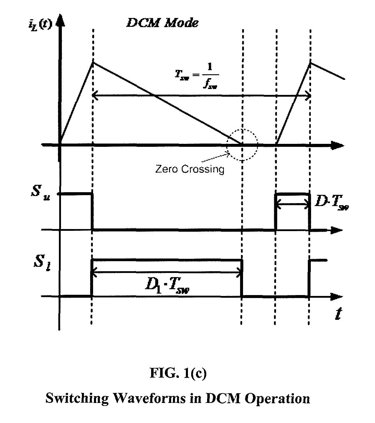
[0010]In one aspect, the inductor current zero crossing point can be interpreted from a pulse-width modulation (PWM) duty cycle value (which is an available parameter in a digital controller and need no additional sensing) during DCM operation. The operation and turn off time of the SR for higher efficiency can also be interpreted from the PWM duty cycle value in DCM mode. In other words, the value of the lower switch ON time (or duty cycle D1) is made as a function of the value of the upper switch ON time (or duty cycle D) which is determined by the output voltage regulation closed loop. Therefore, the DCM mode can be implemented with no need for inductor current sensing, resulting in lower controller power consumption, higher power conversion efficiency, lower sensitivity to noise, and lower size and cost (by reducing the number of components).

Problems solved by technology

The challenges associated with this include inductor current zero crossing point sensing accuracy, noise effect near the zero crossing point and the sensing circuitry speed and power loss.
This requires sensing the instantaneous inductor current information at the switching frequency speed, its accuracy and stability is sensitive to noise effect at the zero crossing transition point and it results in additional power losses by the sensing circuitries especially at higher load currents and at higher switching frequencies.
Moreover, the switching noise, which is introduced at the instances of turning ON and OFF of the converter switches (where the zero crossing of inductor current occurs), makes it more difficult to detect the zero crossing time (and the non zero crossing) accurately.
Furthermore, the sensing and detection circuitries power losses and sensing accuracy will impact the controller operation accuracy and impact the power conversion efficiency.
This implies high power loss through the sensing (which may include a sensor and an amplifier) and comparator circuitries.
This power loss scales with the switching frequency, and therefore, the higher the switching frequency is (in the future), the higher the sensing power loss.
This also impacts the cost and size of the controller.
Moreover, the operation may be more impacted by the sensing accuracy at such frequencies as mentioned earlier.
Moreover, if the implantation utilizes a fully digital controller, an additional ADC (Analog-to-Digital Converter) may be required which means additional size, cost, and power consumption (as explained in references [6, 7] listed on page 12).

Method used


Image

  • Sensor-less operation and detection of CCM and DCM operation modes in synchronous switching power converters
  • Sensor-less operation and detection of CCM and DCM operation modes in synchronous switching power converters
  • Sensor-less operation and detection of CCM and DCM operation modes in synchronous switching power converters

Examples


Embodiment Construction

[0019]Before the present methods and systems are disclosed and described, it is to be understood that the methods and systems are not limited to specific synthetic methods, specific components, or to particular compositions. It is also to be understood that the terminology used herein is for the purpose of describing particular embodiments only and is not intended to be limiting.

[0020]As used in the specification and the appended claims or inventive concepts, the singular forms “a,”“an” and “the” include plural referents unless the context clearly dictates otherwise. Ranges may be expressed herein as from “about” one particular value, and / or to “about” another particular value. When such a range is expressed, another embodiment includes from the one particular value and / or to the other particular value. Similarly, when values are expressed as approximations, by use of the antecedent “about,” it will be understood that the particular value forms another embodiment. It will be further...


PUM


Abstract

Generally, described herein are embodiments of control schemes for sensor-less operation and detection of CCM and DCM in a switching power converter. In one aspect, embodiments of a controller are described that utilize dual control loops and do not require sensing the inductor current or any current in the converter which eliminates or reduces the challenges and problems associated with current sensing. Advantages of embodiments of methods described herein become more significant when used in ultra high switching frequency converters since embodiments of the controller result in eliminating the need for high-speed low-noise current sensing circuitries, when used in on-chip integrated power converters where sensing accuracy may be a more significant issue compared to on-board power converters, and in power converters with paralleled modules since embodiments of the controller eliminate sensing circuitries in each of the modules.

Description

CROSS-REFERENCE TO RELATED APPLICATIONS[0001]This application is a National State Entry of PCTUS10 / 20883 filed Jan. 13, 2010 which claims priority from Provisional Application No. 61 / 144,287 filed Jan. 13, 2009, both of which are incorporated herein by reference in their entirety.FIELD[0002]Embodiments of the invention relate, generally, to systems and methods for the control of power converters.BACKGROUND[0003]Switching power converters with synchronous rectification utilize switching between inductor's current continuous and discontinuous conduction operation modes (CCM and DCM) in order to achieve improved power efficiency across wide load and input voltage ranges. The inductor current zero crossing is sensed in order to detect the operation modes transition point between CCM and DCM. The challenges associated with this include inductor current zero crossing point sensing accuracy, noise effect near the zero crossing point and the sensing circuitry speed and power loss. Moreover,...

Claims


Application Information

Patent Timeline
Patent Type & Authority Patents(United States)
IPC IPC(8): H02M3/156
CPCH02M3/156Y02B70/1466H02M3/1588Y02B70/10
Inventor ABU, QAHOUQ, JABER, A.
Owner UNIVERSITY OF ALABAMA
Learn More