
Sensing coil and sensing unit for sagnac optical fibre current sensor

Active Publication Date: 2013-09-24
SMART DIGITAL OPTICS
View PDF8 Cites 1 Cited by
  • Summary
  • Abstract
  • Description
  • Claims
  • Application Information

AI Technical Summary

Benefits of technology

[0017]The sensing unit as above defined has the current conductor portions and the sensing coil loops arranged and disposed such that, when the sensing unit is connected in circuit with a current-carrying busbar, the two conductor portions of the current conductor provide effectively for increased current sensitivity whilst the dual-loop sensing coil provides for minimal sensitivity to rotational movement.
[0019]The carrier in one embodiment of the sensing unit may optionally comprise first and second spaced-apart conductor members which are connectable in series with the busbar and which respectively are secured to the first and second conductor portions. Also, the first and second conductor portions may be formed as projections (for example, solid cylindrical projections) of a common plate portion of the carrier and, in this embodiment of the invention, the sensing coil may be carried between the conductor members and the common plate. Insulating gaskets may be provided between various ones of the sensing unit components so that a series circuit is formed between the first and second conductor members by way of the first (cylindrical) conductor portion, the common plate and the second (cylindrical) conductor portion. Thus, when the sensing unit is connected in an active electrical circuit, current flow will effectively be in opposite directions through the first and second conductor portions.

Problems solved by technology

Current measuring by known Sagnac interferometers is adversely affected by rotational movement of the sensing coil about a normal to the plane of the coil and it has been determined by the Inventor that a small rotational movement (created, for example, by a 50 Hz or a 60 Hz mechanical vibration) can produce a large phase shift in polarisation modes relative to that produced by a change in magnetic field and, hence, current magnitude.

Method used


Image

  • Sensing coil and sensing unit for sagnac optical fibre current sensor
  • Sensing coil and sensing unit for sagnac optical fibre current sensor
  • Sensing coil and sensing unit for sagnac optical fibre current sensor

Examples


Embodiment Construction

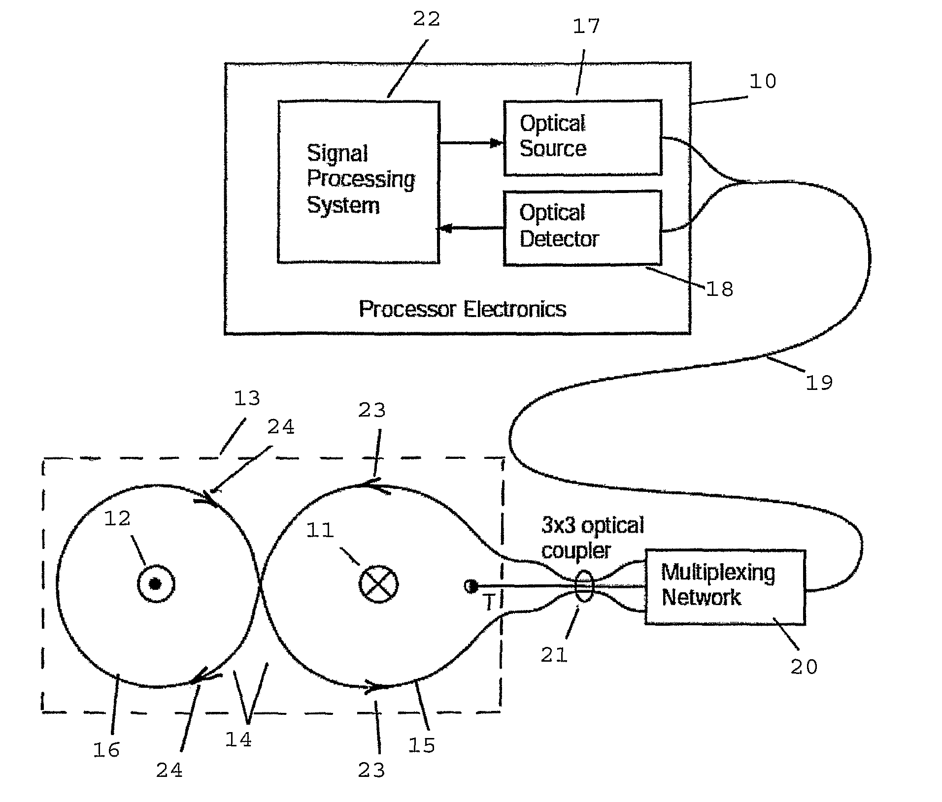
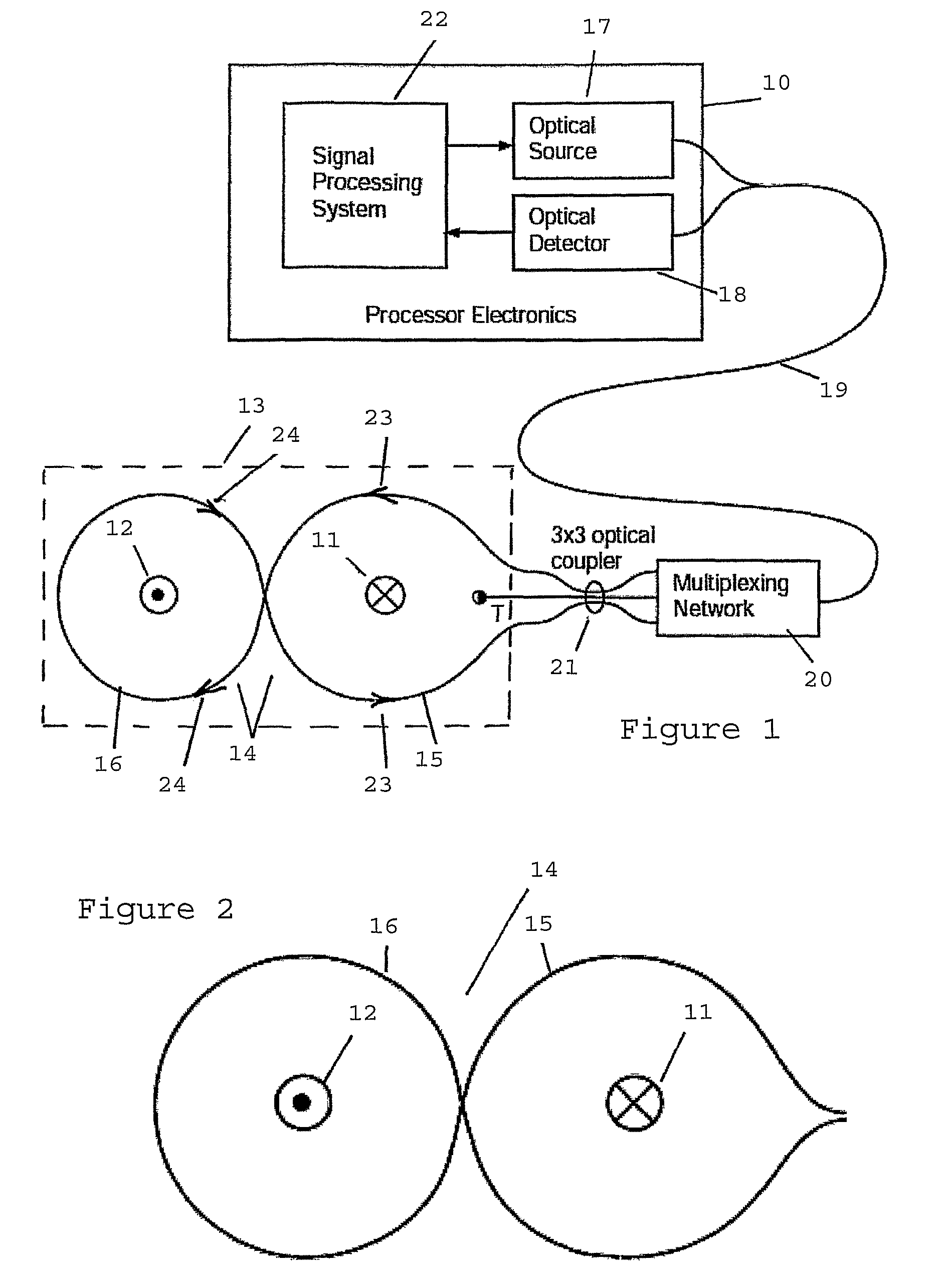
[0028]As illustrated in FIG. 1, the current sensor comprises, in general, a processor 10 in which optical signals are generated, received and processed to provide a measure of sensed electrical current flow through a two-part conductor 11 / 12, and a sensing unit 13. One embodiment of the sensing unit 13 is to be described in more detail with reference to FIG. 5 but, in a general sense, it comprises a sensing coil 14 having two interconnected loops 15 and 16 which enclose the respective conductor portions 11 and 12. The two loops 15 and 16 of the sensing coil 14 are located substantially in a common plane, and the two conductor portions 11 and 12, which have spaced-apart parallel axes, extend orthogonally through the respective loops 15 and 16.

[0029]The sensing coil 14 is connected to an optical source 17 and to an optical detector 18 of the processor 10 by way of a length of duplex single mode optical fibre 19 and further by way of a multiplexing network 20 and a 3×3 optical coupler ...


PUM


Abstract

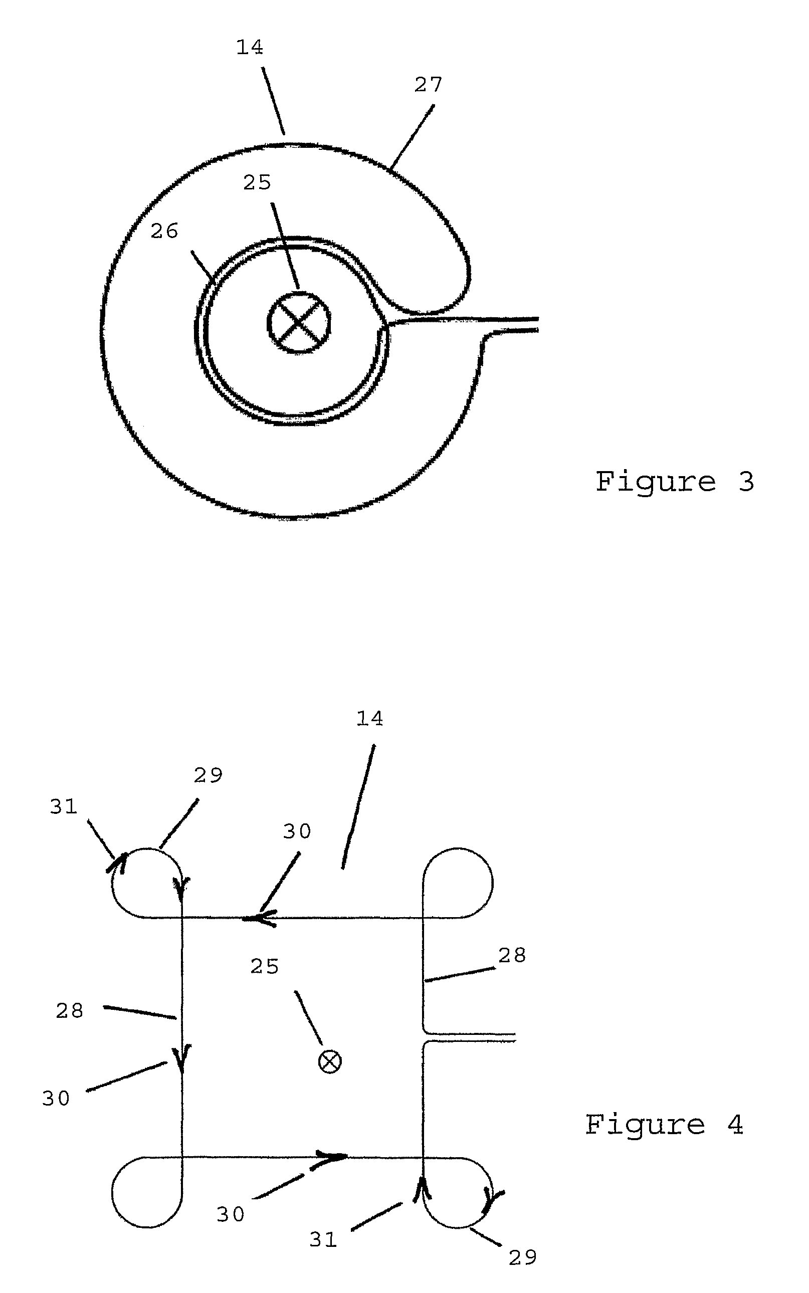
A sensing coil for a Sagnac interferometer current sensor is disclosed, the sensing coil (14) being composed of an optical fiber (for example a spun polarizing Hi-Bi fiber) that is arranged in use to transmit a single elliptical polarization state and the sensing coil comprising at least two interconnected loops (15 and 16 or 26 and 27 or 28 and 29). At least one of the loops is arranged in use to enclose a current conductor (11, 12 or 25) and the loops are interconnected such that light propagating in a first direction (23 or 30) in the first loop will propagate in a second, opposite, direction (24 or 31) in the other or, if more than one, in each other loop, whereby the sensing coil provides minimal sensitivity to rotational movement. Also disclosed are a sensing unit (FIG. 5) that incorporates the sensing coil and a current sensor (FIG. 1) that incorporates the sensing unit.

Description

CROSS-REFERENCE TO RELATED APPLICATIONS[0001]This is the national stage of International Application No. PCT / AU2009 / 000200, filed on Feb. 20, 2009, which claims the benefit of Australian Patent Application No. 2008900845, filed on Feb. 22, 2008 and Australian Patent Application No. 2008900844, filed on Feb. 22, 2008, the contents of all of which are incorporated herein by reference.FIELD OF THE INVENTION[0002]This invention relates to a sensing coil for use in a Sagnac interferometer optical fibre current sensor and, in alternative embodiments, to a current sensor incorporating such sensing coil, to a sensing unit incorporating the sensing coil and to a current sensor incorporating the sensing unit.BACKGROUND OF THE INVENTION[0003]Sagnac interferometer optical fibre current sensors of various types are well known. U.S. Pat. No. 5,677,622 granted to the University of Sydney as assignee of Ian G. Clarke discloses one such current sensor and it comprises a single sensing coil of spun s...

Claims


Application Information

Patent Timeline
Patent Type & Authority Patents(United States)
IPC IPC(8): G01B9/02
CPCG01R15/245
Inventor HAYWOOD, JOHN
Owner SMART DIGITAL OPTICS
Learn More