Carbon dioxide capture power generation system
a technology of power generation system and carbon dioxide, which is applied in the direction of emission prevention, separation process, lighting and heating apparatus, etc., can solve the problems of corroding of the members and preventing the continuous running of carbon dioxide capture equipment, so as to prevent the corrosion of the members in the long run
- Summary
- Abstract
- Description
- Claims
- Application Information
AI Technical Summary
Benefits of technology
Problems solved by technology
Method used
Image
Examples
embodiment 1
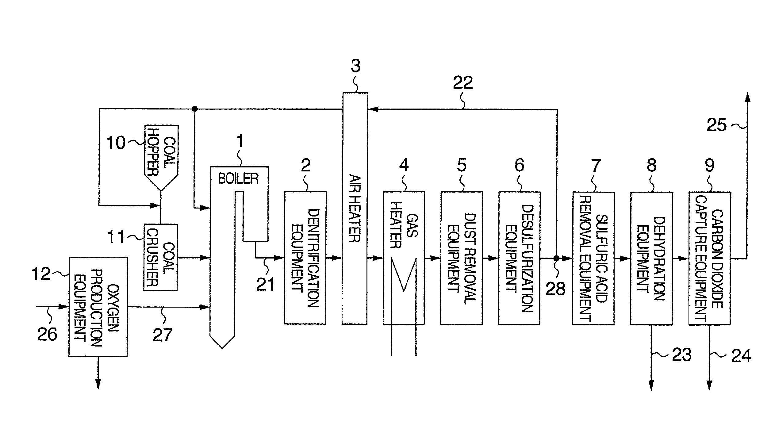
[0028]Taking a coal thermal power generation system using pulverized coal as a fuel as an example, the carbon dioxide capture power generation system according to the present invention is represented in FIG. 1. In the wake flow of a boiler 1 in which the pulverized coal is combusted, a denitrification equipment 2 to reduce the NOx to nitrogen, an air heater 3 and a gas heater 4 to recover the heat of the combustion exhaust gas, and in the wake flow of that, exhaust gas treatment equipments of a dust removal equipment 5 to remove coal ash and a desulfurization equipment 6 to remove the SOx, a sulfuric acid removal equipment 7 to remove the sulfuric acid, a dehydration equipment 8 to remove water, and a carbon dioxide capture equipment 9 to capture carbon dioxide are provided.
[0029]An oxygen production equipment 12 takes in air 26, produces oxygen 27, and supplies the oxygen 27 to the boiler 1. Coal transferred from a coal hopper 10 storing the coal is pulverized by a coal crasher 11,...
embodiment 2
[0048]Although the used sulfuric acid adsorbent becomes a waste, if the adsorbent is of same carbonaceous one such as coal, like activated carbon, the adsorbent can be used as a fuel instead of becoming a waste.
[0049]Further, since the sulfuric acid adsorbed by the sulfuric acid adsorbent is emitted in the combustion exhaust gas as the SOx instead of the sulfuric acid gas by high-temperature combustion at 1,000° C. or higher, it does not result in an increase of the concentration of the sulfuric acid gas. In addition, since the concentration of the sulfuric acid gas in the combustion exhaust gas is as low as several % of the SOx concentration, an extreme increase of the SOx concentration is not avoided.
[0050]As mentioned above, the sulfuric acid adsorbent is desirably the carbonaceous one, and coal, which is a fuel, can be used in the coal thermal power generation system. Further, since mixed combustion of coal and biomass has been implemented in the coal thermal power generation, t...
embodiment 3
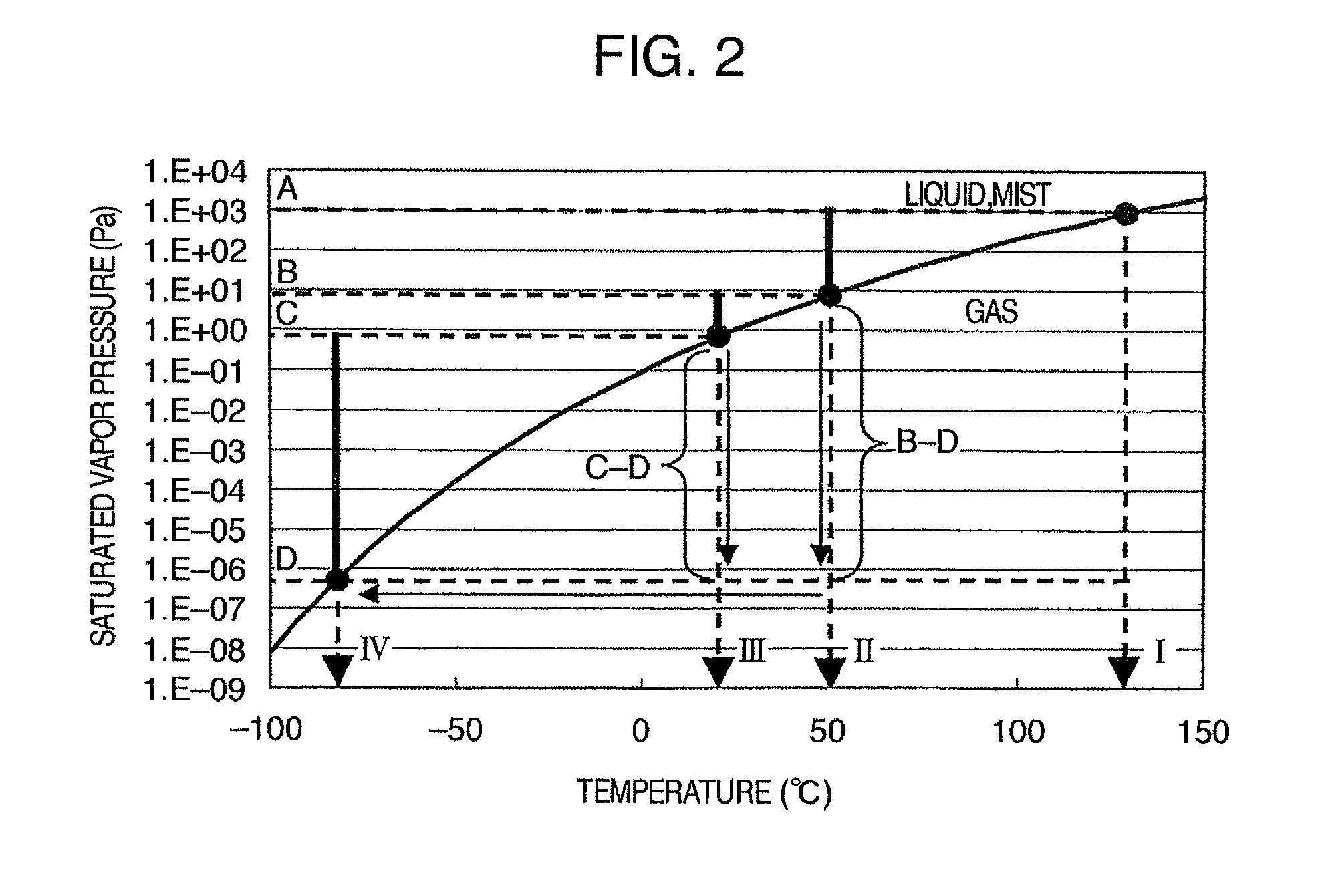
[0055]The combustion exhaust gas of coal contains mercury gas. The mercury gas also liquefies by a decrease in temperature in the same way as sulfuric the acid gas does, and adheres to the members of equipments to cause the corrosion of the members.
[0056]Since the activated carbon, coal or biomass fuel of the sulfuric acid adsorbent can also adsorb the mercury gas in the combustion exhaust gas, the absorbent can prevent liquefaction of the mercury in the equipment in the wake flow of the sulfuric acid removal equipment, for example, in the carbon dioxide capture equipment which is cooled down to −80° C. or lower to protect the equipment members.
[0057]However, the sulfuric acid adsorbent containing adsorbed sulfuric acid deteriorates in the adsorption ability for the mercury gas. In particular, when the sulfuric acid adsorbent adsorbs the sulfuric acid mist in a liquid state, the adsorption ability for the mercury gas deteriorates extremely, because the surface of the sulfuric acid a...
PUM
| Property | Measurement | Unit |
|---|---|---|
| temperature | aaaaa | aaaaa |
| temperature | aaaaa | aaaaa |
| temperature | aaaaa | aaaaa |
Abstract
Description
Claims
Application Information
 - R&D
- Intellectual Property
- Life Sciences
- Materials
- Tech Scout
- Unparalleled Data Quality
- Higher Quality Content
- 60% Fewer Hallucinations
Browse by: Latest US Patents, China's latest patents, Technical Efficacy Thesaurus, Application Domain, Technology Topic, Popular Technical Reports.
© 2025 PatSnap. All rights reserved.Legal|Privacy policy|Modern Slavery Act Transparency Statement|Sitemap|About US| Contact US: help@patsnap.com


