Bone plate and screw retaining mechanism

a technology of screw retaining mechanism and bone screw, which is applied in the field of bone screw retaining mechanism, can solve the problems of bone screw slipping or pulling away, limiting the potential application of bone fixation plate, and potentially serious problems

Inactive Publication Date: 2013-08-06
AESCULAP IMPLANT SYST
View PDF21 Cites 13 Cited by
  • Summary
  • Abstract
  • Description
  • Claims
  • Application Information

AI Technical Summary

Benefits of technology

[0019]According to the present invention, there is provided a bone plate assembly utilizing at least one bone screw for fixation of adjacent bones of a spine including a base plate having at least one aperture extending therethrough and a screw retaining mechanism mounted and movable on the plate between locked and unlocked positions relative to the aperture for preventing the bone screw from backing out from the base plate. The present invention also provides for a device for placement into an aperture of a base plate including a screw retaining mechanism mountable and movable on a plate between locked and unlocked positions relative to an aperture for preventing a bone screw from backing out from the base plate. Additionally, the present invention provides for a snap ring for placement into an aperture of a base plate including a screw retaining mechanism mountable and movable on the plate between locked and unlocked positions relative to the aperture for preventing a screw from backing out from the base plate. Also, the present invention provides for a device for placement into an aperture of a base plate, wherein the aperture includes a pocket, the device including a screw retaining mechanism mountable and movable on the plate between locked and unlocked positions relative to the aperture for preventing a screw from backing out from the base plate. Finally, the present invention provides for a bone plate assembly utilizing at least one bone screw for fixation of adjacent vertebrae of a spine including a base plate having at least one aperture extending therethrough, wherein at least one aperture is an elongated slot having a hole extending therethrough and walls forming a spherical seat a distance along a length of the slot to allow the screw to enter through the hole and screw retaining mechanism mounted and movable on the plate between locked and unlocked positions relative to the aperture for preventing the bone screw from backing out from the base plate.

Problems solved by technology

A common problem associated with the use of such bone fixation plates is a tendency of the bone screws to “back out” or pull away from the bone onto which they were fixed.
This problem occurs primarily due to the normal motion of the body and the spine.
Since the spine is a very dynamic entity and is constantly moving, this problem is especially prevalent in areas of high stress such as the spine.
This creates a number of potentially serious problems given the number and proximity of blood vessels and other critical structures near the locations of spinal fixation plate assemblies.
For this locking mechanism to work however, the distance between the heads of the bone screws must be kept to a minimum, thereby limiting the potential applications of the bone fixation plate.
Additionally, while the Lowery et al. patent allows for the bone screws to be angled, if the screws are not angled exactly the same amount, which is very difficult to achieve, the locking screw cannot adequately contact both bone screw heads.
This problem can cause inferior fixation of the bone or even total failure of the fixation.
All of these particular designs have drawbacks including potential for breakage or requiring particular precision and alignment in their application in order to correctly work.
The end result is the screw penetrates through the plate and creates an unnecessary load against the vertebrate, which opposes the bone screws and tends to try and lift the plate off the bone.
As a result, stress is created in the metal and mostly will possibly require the replacement of the plate.

Method used


Image

  • Bone plate and screw retaining mechanism
  • Bone plate and screw retaining mechanism
  • Bone plate and screw retaining mechanism

Examples


Embodiment Construction

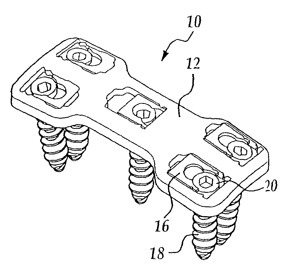
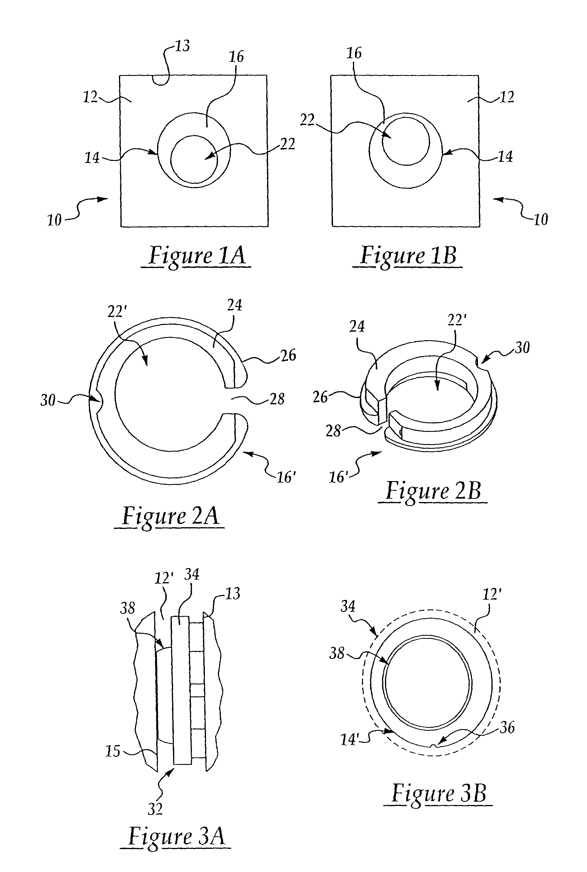
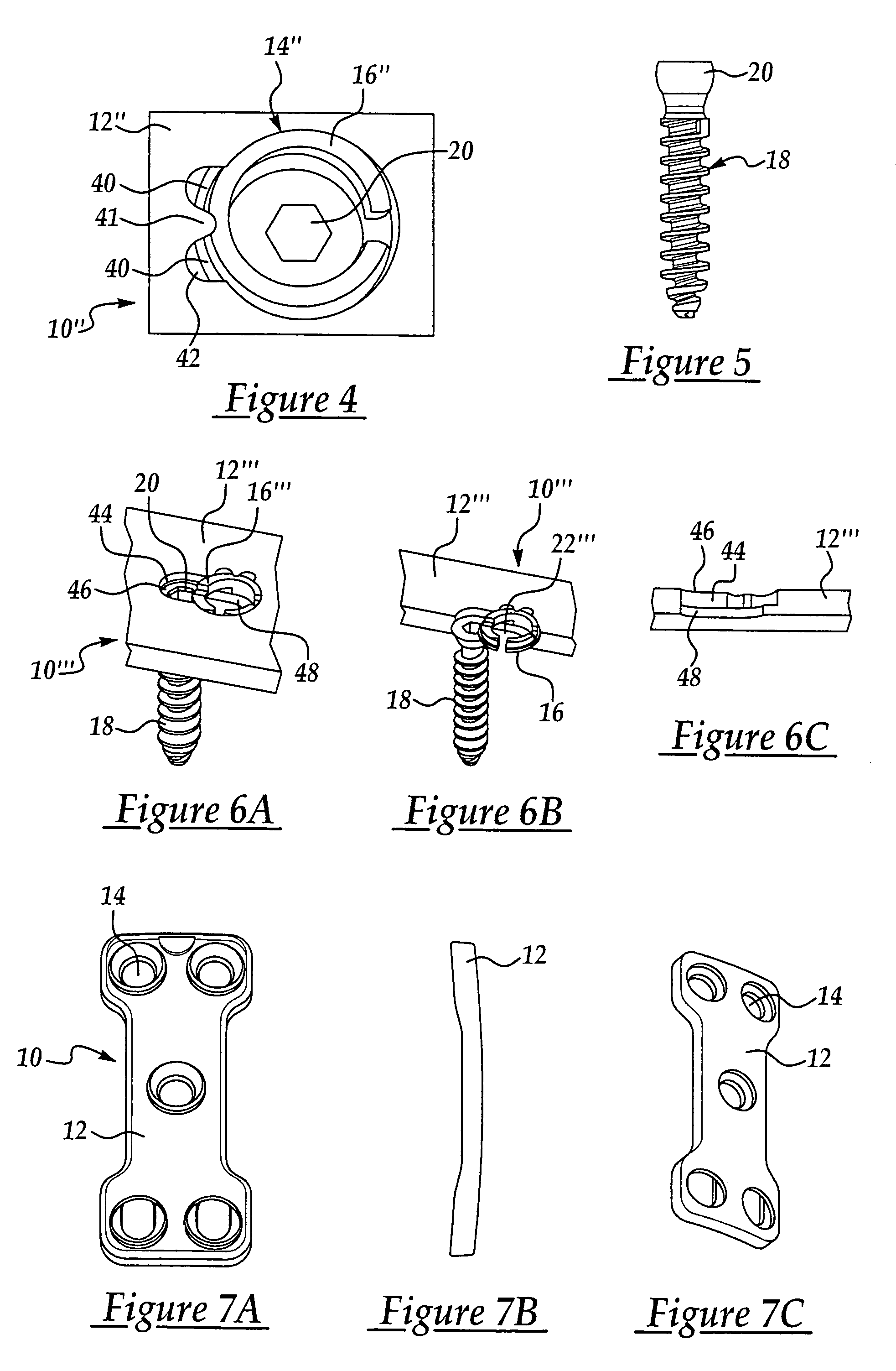
[0042]A bone plate assembly constructed in accordance with the present invention is generally indicated by 10 in the figures. Generally, the bone plate assembly 10 includes a base plate 12 having at least one aperture 14 extending therethrough and a screw retaining mechanism 16. The bone plate assembly 10 utilizes at least one bone screw 18 for the fixation of bones, and more specifically adjacent vertebrae. The key feature of the present invention is not only the bone plate assembly 10, but also the screw retaining mechanism 16. The screw retaining mechanism 16 prevents the bone screw 18 from backing out from its fixed position within the aperture 14 of the base plate 12 and within the bone. Although there are numerous embodiments of both the bone plate assembly 10 and the screw retaining mechanism 16, they all have the common characteristic of being able to cover at least a portion of the bone screw 18 after the screw 18 is inserted and turned into its fixed position within the ba...


PUM


Abstract

A bone plate assembly utilizing at least one bone screw for fixation of adjacent bones of a spine including a base plate having at least one aperture extending therethrough and screw retaining mechanism mounted and movable on the plate between locked and unlocked positions relative to the aperture for preventing the bone screw from backing out from the base plate.

Description

CROSS-REFERENCE TO RELATED APPLICATIONS[0001]This application is a divisional application of U.S patent application Ser. No. 10 / 095,720, filed Mar. 12, 2002, now U.S. Pat. No. 6,695,846 which is incorporated herein by reference.BACKGROUND OF THE INVENTION[0002]1. Field of the Invention[0003]The present invention relates to bone fixation plate assemblies. More specifically, the present invention relates to a mechanism for preventing the displacement of a screw.[0004]2. Description of Related Art[0005]Spinal fixation has become a common approach in treating spinal disorders, fractures, and for fusion of vertebrate. A common devise used for spinal fixation is a bone fixation plate assembly. Typical bone fixation plate assemblies have a relatively flat, rectangular plate with a plurality of apertures therethrough. Fasteners, such as bone screws, are utilized to secure the bone fixation plate assembly. The screws are firmly tightened to secure the bone fixation plate to the bone or bones...

Claims


Application Information

Patent Timeline
Patent Type & Authority Patents(United States)
IPC IPC(8): A61B17/56A61F2/30A61B17/80A61B17/58A61B17/70
CPCA61B17/7059A61B17/8042
Inventor RICHELSOPH, MARCADAMS, JAY
Owner AESCULAP IMPLANT SYST
Why Eureka
Try Eureka