Method for deploying climate sensor in indoor space and storage medium for storing thereof

a technology for climate sensors and indoor spaces, applied in the direction of heat measurement, instruments, machines/engines, etc., can solve the problems of increasing the power consumption of the central air conditioner, uneven temperature distribution in buildings with large indoor spaces, and uncomfortable people inside buildings with large spaces

Inactive Publication Date: 2013-01-01
INSTITUTE FOR INFORMATION INDUSTRY
View PDF7 Cites 3 Cited by
  • Summary
  • Abstract
  • Description
  • Claims
  • Application Information

AI Technical Summary

Problems solved by technology

However the temperature inside buildings with large indoor spaces is not distributed evenly.
Therefore, the adjustments to the temperature often makes people inside buildings with large spaces uncomfortable and more power is consumed by the central air conditioning since the central air conditioning is controlled according to temperature measured by evenly deployed temperature sensors.

Method used


Image

  • Method for deploying climate sensor in indoor space and storage medium for storing thereof
  • Method for deploying climate sensor in indoor space and storage medium for storing thereof
  • Method for deploying climate sensor in indoor space and storage medium for storing thereof

Examples


Embodiment Construction

[0014]Reference will now be made in detail to the present embodiments of the invention, examples of which are illustrated in the accompanying drawings. Wherever possible, the same reference numbers are used in the drawings and the description to refer to the same or like parts.

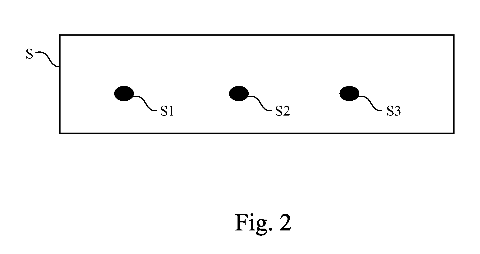
[0015]FIG. 1 is a flow diagram of a method for deploying at least one climate sensor in an indoor space according to one embodiment of this invention. FIG. 2 is an embodiment of an indoor space. In the method for deploying at least one climate sensor in an indoor space, at least one candidate deploy point, the climate property of which differs the least from the other candidate deploy points, is selected. Then, at least one climate sensor is deployed at the selected candidate deploy point. The climate sensor may be a temperature sensor, a humidity sensor, a light sensor or other types of climate sensors. The method for deploying at least one climate sensor in an indoor space may take the form of a computer pro...


PUM


Abstract

A method for deploying at least one climate sensor in an indoor space includes: several candidate deploy points in the indoor space are obtained. Climate properties at the candidate deploy points are obtained. Deploy-point-number limit is obtained. Available deploy point sets, which conform to the deploy-point-number limit, are generated according to the candidate deploy points. Climate-property differences of the available deploy point sets are calculated according to the climate properties at the candidate deploy points. The climate-property differences of the available deploy point sets are differences between the climate properties at the available deploy point sets and those at the candidate deploy points. A target deploy point set, climate-property difference of which is the least among those of the available deploy point sets, is selected from the available deploy point sets. At least one first climate sensor is deployed at the target deploy point of the target deploy point set.

Description

RELATED APPLICATIONS[0001]This application claims priority to Taiwan Application Serial Number 98140171, filed Nov. 25, 2009, which is herein incorporated by reference.BACKGROUND[0002]1. Technical Field[0003]The present invention relates to a method for deploying sensors and a storage medium for storing thereof. More particularly, the present invention relates to a method for deploying at least one climate sensor in an indoor space and a storage medium for storing thereof.[0004]2. Description of Related Art[0005]As building techniques improve, buildings are often built with large indoor spaces. To make people feel comfortable staying in buildings with large indoor spaces, many machines, such as central air conditioning or lamps, maintain a comfortable man-made climate indoors.[0006]Since operational status of central air conditioning is controlled according to indoor temperature, many temperature sensors are deployed in buildings with large indoor spaces for measuring indoor tempera...

Claims


Application Information

Patent Timeline
Patent Type & Authority Patents(United States)
IPC IPC(8): G01F17/00
CPCG01W1/17
Inventor SUNG, JING-TIAN
Owner INSTITUTE FOR INFORMATION INDUSTRY
Why Eureka
Try Eureka