
Device and method for monitoring a fuel metering system

a fuel metering and device technology, applied in the direction of fluid tightness measurement, electrical control, instruments, etc., can solve the problems of pressure-dependent leak widening or leak shrinkage, and achieve the effect of reliable recognition

Inactive Publication Date: 2012-06-05
ROBERT BOSCH GMBH
View PDF15 Cites 3 Cited by
  • Summary
  • Abstract
  • Description
  • Claims
  • Application Information

AI Technical Summary

Benefits of technology

[0003]According to the present invention it is recognized that different errors result in different pressure variations. In particular, it is recognized that leaks differ by the type of flow. A distinction is made in particular between laminar and turbulent flows. Furthermore, pressure-dependent leak widenings or leak shrinkages are possible. This means that the cross-section area of the leak opening varies as a function of the pressure. This provides the possibility of recognizing the type of leak from the shape of the pressure drop curve. By associating the measured pressure variation with predefined pressure variations which occur in the event of certain types of leaks or in the event of a defect of different components, the error may be reliably associated with a certain type of error and therefore with the defective component. This means that the type of error and thus the defective component may be reliably recognized from the pressure curve. In particular this procedure makes a considerably more reliable leak detection possible. Using the conventional procedure, in the event of a difference, a leak is also detected in each case. Using the invention, certain pressure curves not resulting from a leak but that would be identified as a leak in the related art are reliably recognized as such. Unnecessary error responses such as, for example, replacement of components, may thus be avoided.

Problems solved by technology

Furthermore, pressure-dependent leak widenings or leak shrinkages are possible.
This means that the type of error and thus the defective component may be reliably recognized from the pressure curve.

Method used


Image

  • Device and method for monitoring a fuel metering system
  • Device and method for monitoring a fuel metering system
  • Device and method for monitoring a fuel metering system

Examples


Embodiment Construction

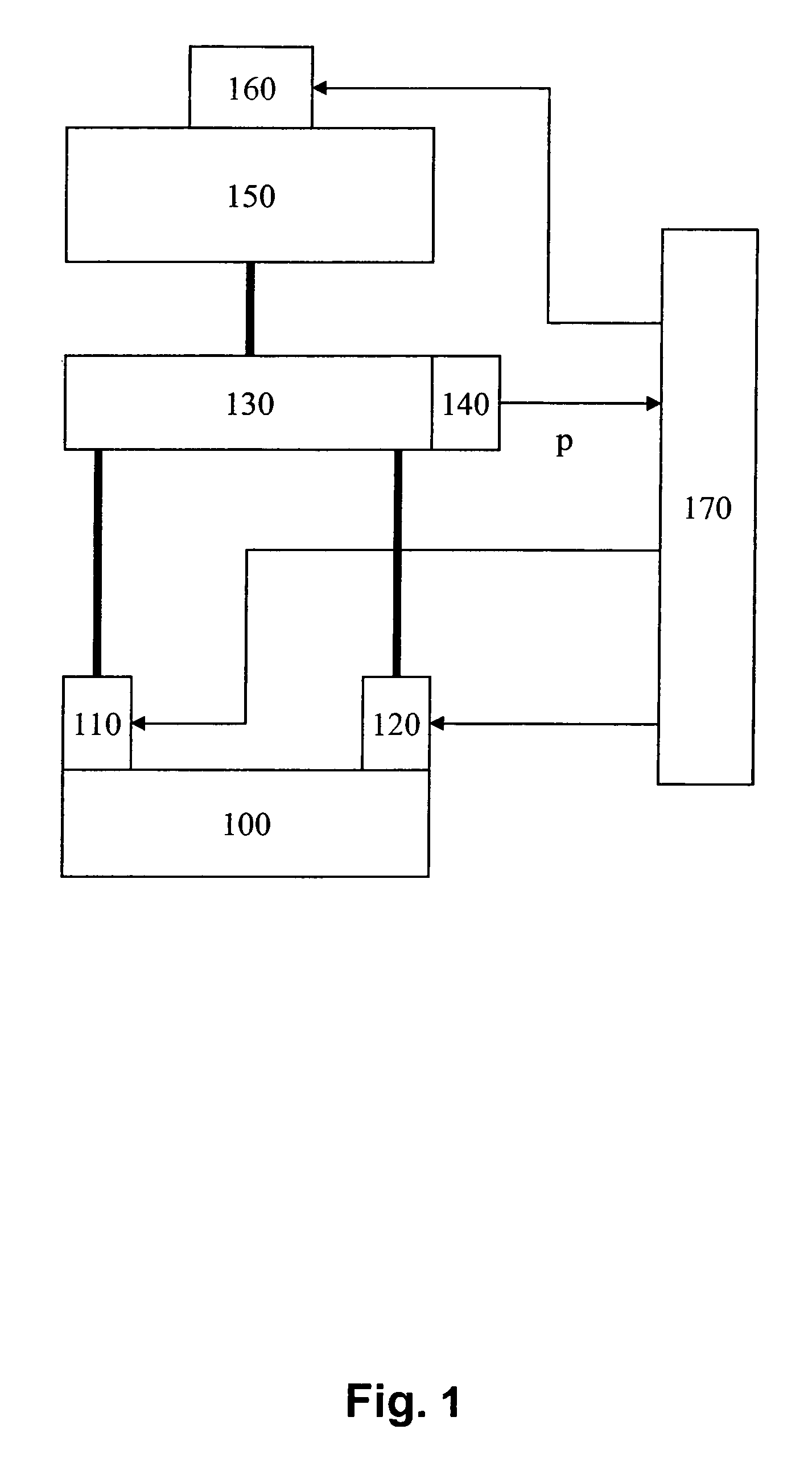
[0008]FIG. 1 shows the important elements of a fuel metering system, of a diesel engine in particular, as an example. The internal combustion engine is labeled with the reference numeral 100. It is supplied with fuel via a first injector 110 and a second injector 120. Injectors 110 and 120 are connected to a rail 130 via fuel lines. At least one sensor 140, which outputs a pressure quantity p characterizing the pressure in the high-pressure zone, is situated on the rail.

[0009]This pressure quantity is also referred to hereinafter as rail pressure. Instead of the output signal of sensor 140, other quantities characterizing the rail pressure may also be similarly analyzed.

[0010]Rail 130 receives fuel from a high-pressure pump 150. This high-pressure pump is associated with an actuating element 160 for controlling the quantity of fuel pumped by high-pressure pump 150, and thus the rail pressure. This actuating element 160, as well as injectors 110 and 120, receive activation signals fr...


PUM


Abstract

A method and device for monitoring a fuel metering system, in which fuel is pumped from a low-pressure zone into a high-pressure zone. The pressure in the high-pressure zone is detected. An error is recognized on the basis of the pressure variation in the high-pressure zone. The type of error is recognized on the basis of the shape of a pressure drop curve. The variation of the pressure quantity over time is approximated using a function such as the hyperbolic function. The type of error is recognized on the basis of the quantity characterizing the function.

Description

BACKGROUND INFORMATION[0001]German Patent No. DE 195 20 300 describes a device for detecting a leak in a fuel supply system in an internal combustion engine, in particular in a compression-ignition internal combustion engine. In the device described therein, the fuel is conveyed by at least one fuel pump under pressure from a fuel reservoir into a so-called high-pressure zone. From the high-pressure zone the fuel reaches the individual combustion chambers of the internal combustion engine via injectors. The pressure in the high-pressure zone is usually detected by a pressure sensor. This pressure sensor is normally used for setting or regulating the pressure in the high-pressure zone. In the related art the pressure is analyzed by detecting the pressure variation and comparing it with an expected pressure variation. In the event of a difference between an expected pressure variation and the actual pressure variation, the device detects a leak.[0002]The disadvantage in this type of e...

Claims


Application Information

Patent Timeline
Patent Type & Authority Patents(United States)
IPC IPC(8): G01M15/09
CPCF02D41/22F02D41/3845F02M63/0225F02M65/003F02D2041/1423F02D2041/224F02D2041/225F02D41/38
Inventor BOSSEMEYER, HANS GEORGHACKNER, MICHAEL
Owner ROBERT BOSCH GMBH
Learn More