
Low profile helmet vents and venting system

a venting system and low-profile technology, applied in the field of helmets, can solve the problems of limited space and the device that delivers air to the top of the head, and achieve the effect of not taking up a lot of space and being low-profil

Inactive Publication Date: 2012-03-06
FOX RACING
View PDF10 Cites 12 Cited by
  • Summary
  • Abstract
  • Description
  • Claims
  • Application Information

AI Technical Summary

Problems solved by technology

This device delivers air to the top of the head and is limited in the manner in which it can cool or dehumidify the interior of the helmet shell.

Method used


Image

  • Low profile helmet vents and venting system
  • Low profile helmet vents and venting system
  • Low profile helmet vents and venting system

Examples


Embodiment Construction

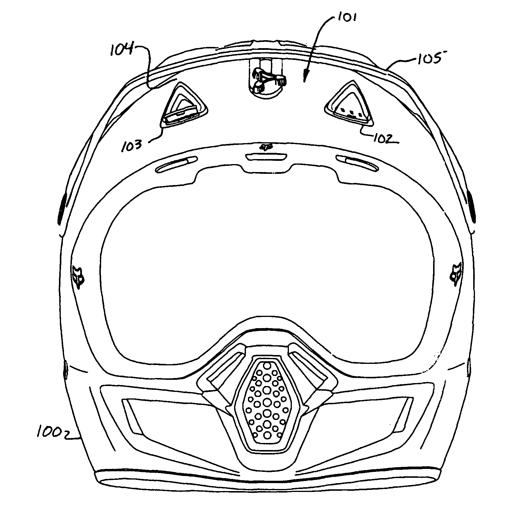
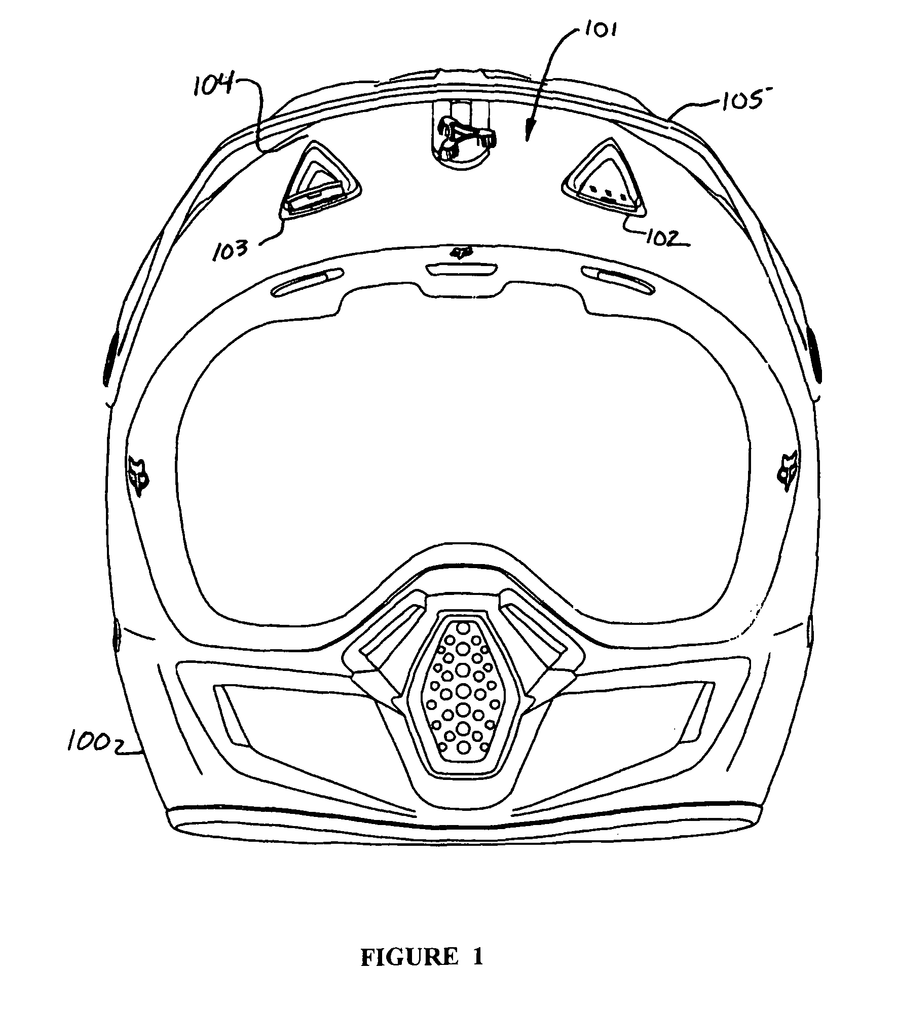
[0018]In some embodiments of the present invention, as seen in FIG. 1, a motorcycle helmet 100 has vents 102, 103 affixed on the outer shell 101 of the helmet. In some embodiments, there are two vents. In some embodiments, there are two vents spaced apart over the forehead of the wearer. In some embodiments, the outer shell 101 of the motorcycle helmet 100 has raised portions 104 adapted for the enhancement of air flow within the helmet. The vents 102, 103 may be placed in the outer shell 101 such that the air flow inlet that the vents provide feeds into an area under the raised portions 104. In some embodiments, a visor 105 is affixed to the helmet 100 in the area adjacent to and above the vents 102, 103. The visor may serve a multitude of functions, including that of a sun shade for the wearer's eyes. The visor 105 may also facilitate air flow into the vents while the user is in forward motion. The visor 105 may also be shaped to enhance air flow into the vents.

[0019]FIGS. 2 and 3...


PUM


Abstract

A motorcycle helmet vent and venting system that is low profile and does not take up much space on the helmet shell. A motorcycle vent that pivots internally to allow air flow and pivots such that the vent tab may penetrate the outer plane of the helmet shell. A motorcycle helmet with raised portions in its shell rearward of vents in the helmet shell.

Description

BACKGROUND OF THE INVENTION[0001]1. Field of Invention[0002]The present invention related generally to the field of helmets, and more specifically to a low profile venting system using helmet vents.[0003]2. Description of Related Art[0004]Safety helmets for motorcycles are typically made in the form of a complete cap that provides an opening in the area of the user's eyes. The helmets are generally provided with an external shell, made from a rigid and strong material, such as polycarbonate, or composite materials, coupled with safety padding inside the shell. The safety padding is often made of expanded polystyrene, expanded polypropylene, or foamed polyurethane, and is itself often lined with a soft material in order to provide comfort to the wearer.[0005]Prior art devices have addressed the need for ventilation in motorcycle helmets. For example, U.S. Pat. No. 5,086,520 to Arai utilizes an air inlet on the top portion of the shell to allow for the introduction of air into the she...

Claims


Application Information

Patent Timeline
Patent Type & Authority Patents(United States)
IPC IPC(8): A63B71/10
CPCA42B3/283
Inventor PIERCE, BRENDAN ERIK
Owner FOX RACING
Learn More