
Three-dimensional location-based texture transfers

a location-based texture and transfer technology, applied in the field of computer-based image generation, can solve the problems of time-consuming and laborious, large change in texture mapping, undesirable distortion,

Active Publication Date: 2011-10-18
DISNEY ENTERPRISES INC
View PDF4 Cites 27 Cited by
  • Summary
  • Abstract
  • Description
  • Claims
  • Application Information

AI Technical Summary

Benefits of technology

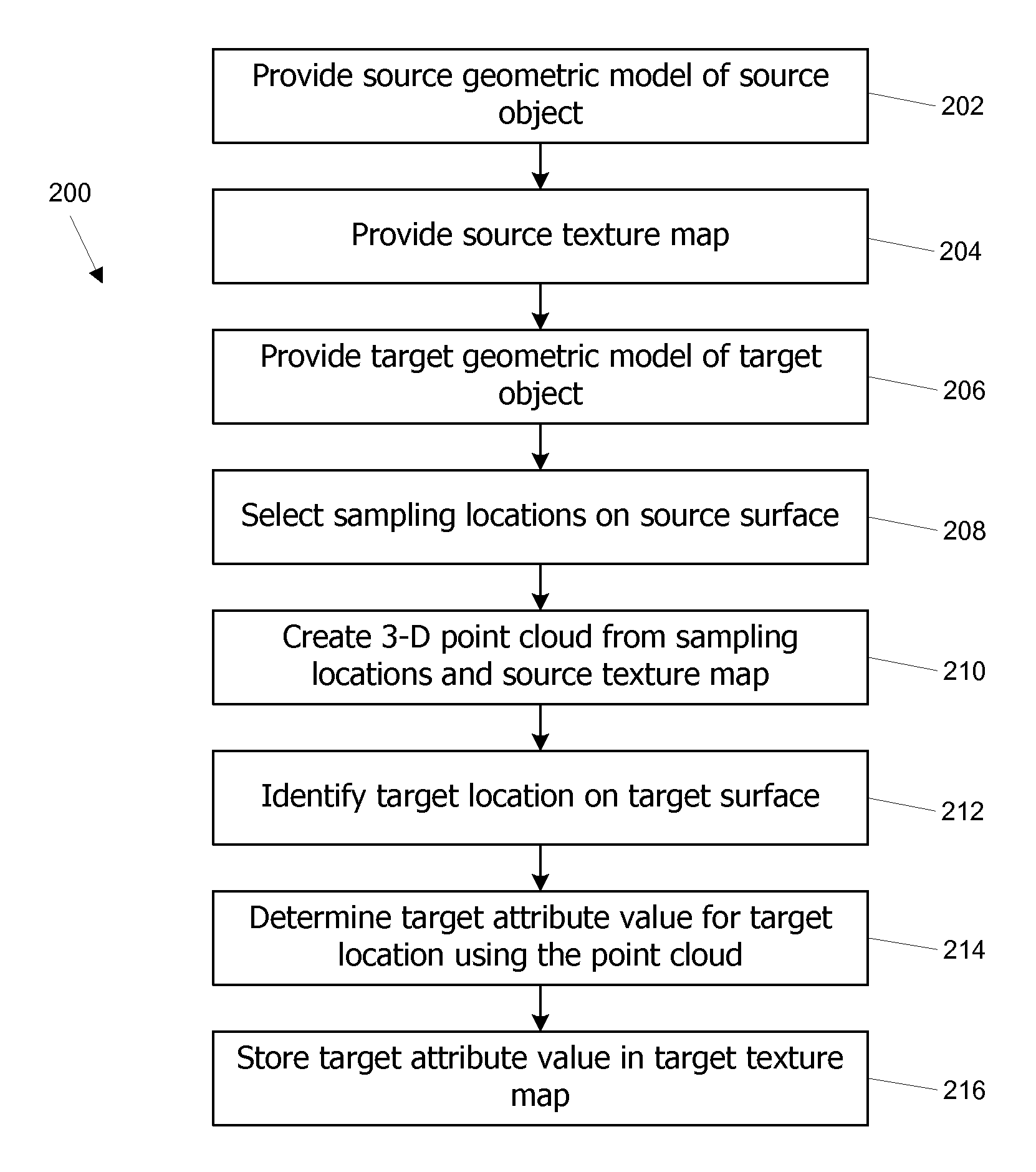
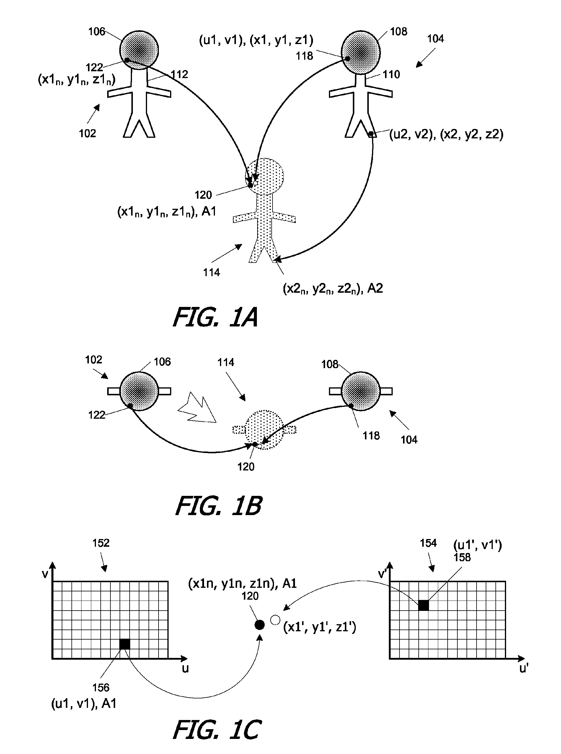
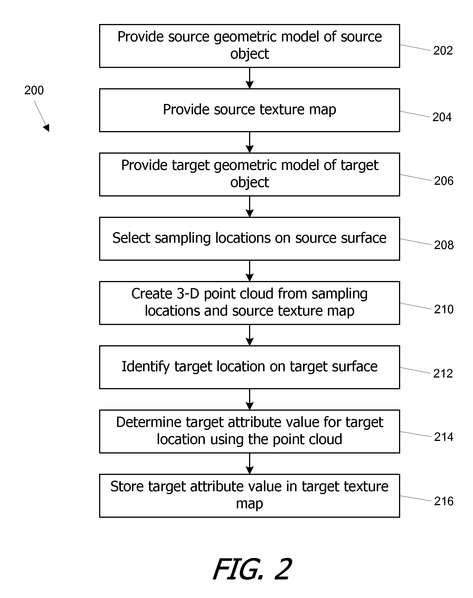
[0009]Embodiments of the present invention provide systems and methods for transferring textures between different object models using a point cloud. In a first phase, a point cloud in 3-D space is created to represent a texture map as applied to a first, or “source,” object model. In some embodiments, the point cloud has the property that each texel of the texture map is represented by a point in the point cloud; for each texel, a corresponding location on a surface in 3-D space defined by the source object model is identified, and the point cloud point has the coordinates of the corresponding location and the attribute value of the texel. An attribute value for a target texel of a texture map associated with a second, or “target,” object model, is determined by identifying the 3-D location on a surface defined by the target object model that maps to the texture-space coordinates of the target texel and assigning an attribute value to the target texel based on the attribute value of the nearest point (or points) to that location in the 3-D point cloud. In this manner, a texture map for the target object model can be automatically populated with texel values. To the extent that differences between the source and target object models are minor (e.g., adding detail or making small modifications to the shape), the texture transfer can be accomplished without loss of information or manual cleanup.

Problems solved by technology

(Sometimes, even a seemingly small modification to the control vertices can result in a large change in the texture mapping.)
If the texture information is not properly transferred from the original texture map to a new texture map associated with the modified model, undesirable distortion can result.
Existing techniques for transferring textures from old geometry to new geometry are time-consuming.
This process is tedious and time-consuming.
This projection technique can save a significant amount of time as compared to manual re-painting, particularly for any portions of the object where geometry was not changed.
However, projection techniques have other drawbacks.
In addition, distortion can result, e.g., if a surface of the object is oriented at an angle to the optical axis of the projection.
Consequently, texture transfers can be accelerated using 2-D projections but often end up requiring extensive manual cleanup.

Method used


Image

  • Three-dimensional location-based texture transfers
  • Three-dimensional location-based texture transfers
  • Three-dimensional location-based texture transfers

Examples


Embodiment Construction

[0019]Embodiments of the present invention provide systems and methods for transferring textures between different object models using a point cloud. In a first phase, a point cloud in 3-D space is created to represent a texture map as applied to a first, or “source,” object model. In some embodiments, the point cloud has the property that each texel of the texture map is represented by a point in the point cloud; for each texel, a corresponding location on a surface in 3-D space defined by the source object model is identified, and the point cloud point has the coordinates of the corresponding location and the attribute value of the texel. An attribute value for a target texel of a texture map associated with a second, or “target,” object model, is determined by identifying the 3-D location on a surface defined by the target object model that maps to the texture-space coordinates of the target texel and assigning an attribute value to the target texel based on the attribute value o...


PUM


Abstract

Textures are transferred between different object models using a point cloud. In a first phase, a point cloud in 3-D space is created to represent a texture map as applied to a first, or “source,” object model. In a second phase, a value for a target texel of a texture map associated with a second, or “target,” object model, is determined by identifying the 3-D location on a surface defined by the target object model that maps to the location of the target texel and assigning a value based on the nearest point (or points) to that location in the 3-D point cloud. To the extent that differences between the source and target object models are minor, the texture transfer can be accomplished without loss of information or manual cleanup.

Description

CROSS-REFERENCES TO RELATED APPLICATIONS[0001]This application claims the benefit of U.S. Provisional Application No. 60 / 951,421, filed Jul. 23, 2007, entitled “Three-Dimensional Location-Based Texture Transfers,” which disclosure is incorporated herein by reference for all purposes.BACKGROUND OF THE INVENTION[0002]The present invention relates in general to computer-based image generation and in particular to transferring textures from one surface to another based on three-dimensional location information.[0003]Computer-based image generation is frequently used to produce animated movies. The characters and other objects that will appear in the movie can be defined as three-dimensional (“3-D”) models that can be placed at various positions within a scene. Generally, the models for characters (and other movable objects) provide enough information to allow the character to be shown from any angle.[0004]Modeling a character or other object usually involves defining the surface geometr...

Claims


Application Information

Patent Timeline
Patent Type & Authority Patents(United States)
IPC IPC(8): G06T17/00G06T11/40G09G5/00G06K9/36G06K9/32A63F13/00
CPCG06T15/04
Inventor BURLEY, BRENTTAPPAN, CHARLESTEECE, DANIEL
Owner DISNEY ENTERPRISES INC
Learn More