Sealed lubrication system and method for dynamic stabilization system
a dynamic stabilization system and sealant technology, applied in the field of sealant lubrication system for dynamic stabilization system, can solve the problems of affecting the loading environment of the disc, affecting the stability of the disc,
- Summary
- Abstract
- Description
- Claims
- Application Information
AI Technical Summary
Benefits of technology
Problems solved by technology
Method used
Image
Examples
first embodiment
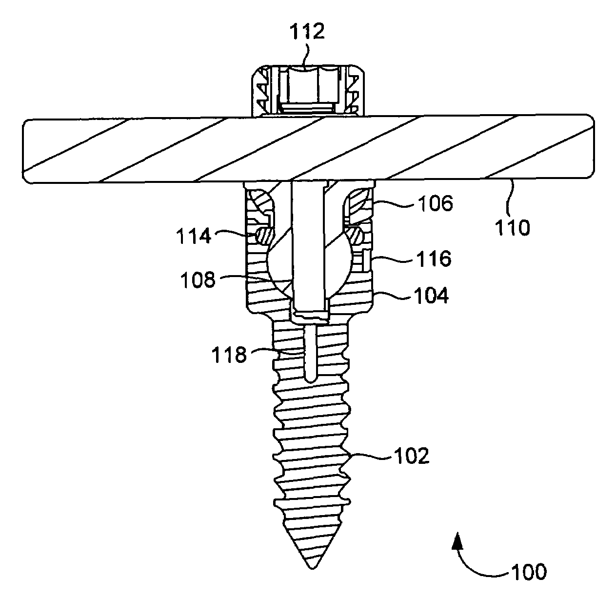
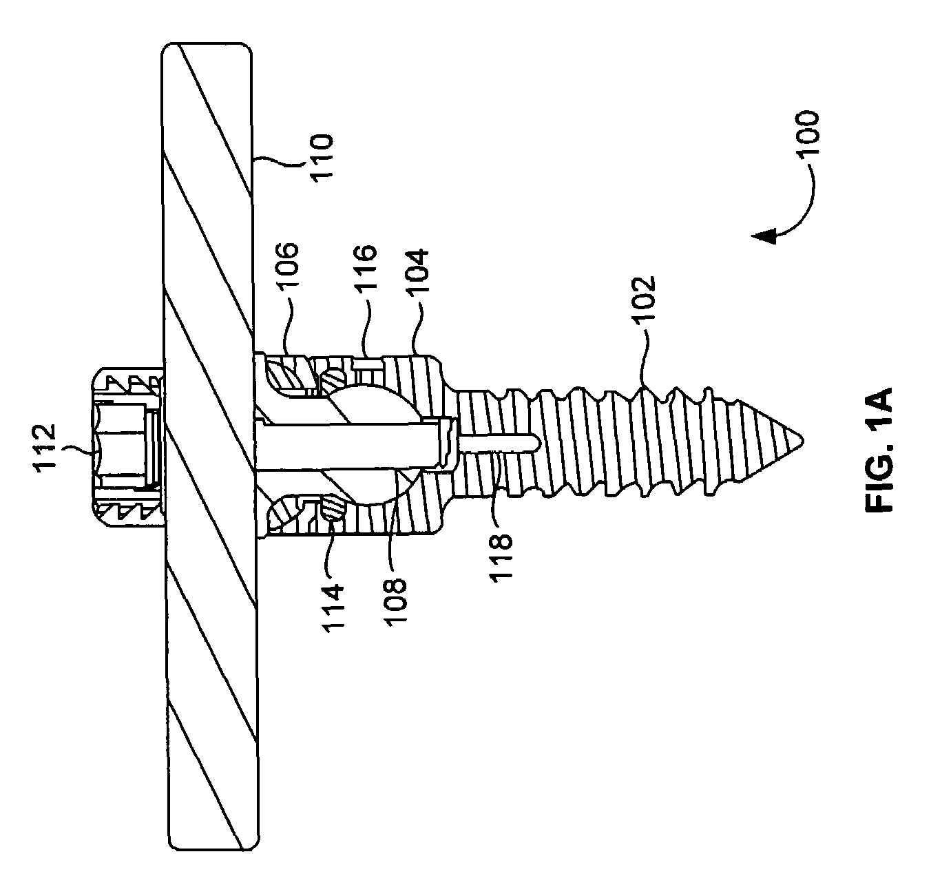
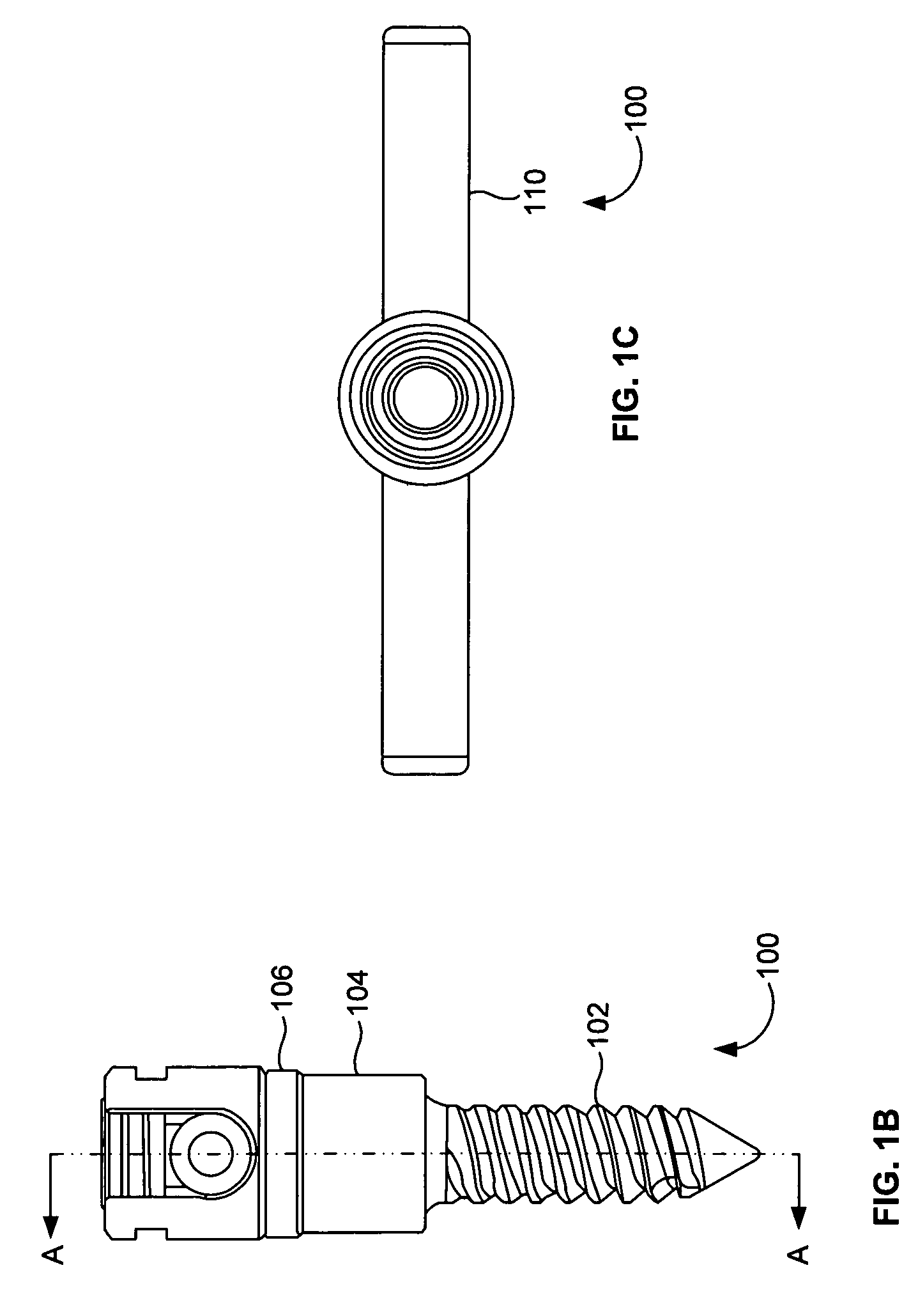
[0040]FIGS. 7A through 7D illustrate a perspective view, a front view, a cross-sectional view, and a top view, respectively, of the bumper 106 of the dynamic screw assembly 100 of FIGS. 1A through 1C herein. In this embodiment, the biased bumper 106A is configured as a bowl-shaped mechanism 115 with an open top 113 and bottom 117. The top 113 bottom 117 of the biased bumper 106 may be beveled to provide the biasing effect.
second embodiment
[0041]FIGS. 8A through 8D illustrate a perspective view, a front view, a cross-sectional view, and a top view, respectively, of the bumper 106 of the dynamic screw assembly 100 of FIGS. 1A through 1C herein. In this embodiment, the biased bumper 106B is configured as a bowl-shaped mechanism 127 with an open top and bottom. A slot 128 is included in the mechanism 127. The upper surface 129 and lower surface 130 of the biased bumper 106C may be angled to provide the biasing effect.
third embodiment
[0042]FIGS. 9A through 9D illustrate a perspective view, a front view, a cross-sectional view, and a top view, respectively, of the bumper 106 of the dynamic screw assembly 100 of FIGS. 1A through 1C herein. In this embodiment, the biased bumper 106C comprises a generally flat top portion 181 with a central bore 121 having a raised surface 125 extending outwardly from the top portion 181. A curved bottom portion 123 of the bumper 106C is defined by opposed curved legs 119, which provides the biasing effect.
[0043]The biased bumper 106 is located between the bone anchor 102 and the coupling member 104. In one embodiment, the bumper 106 coincides with the range of angulation created by the dynamic screw assembly 100.
[0044]FIGS. 10A through 10D illustrate a perspective view, a front view, a cross-sectional view, and a top view, respectively, of the ring member 114 of the dynamic screw assembly 100 of FIGS. 1A through 1C according to an embodiment herein. The ring member 114 fits into t...
PUM
 Abstract
Description
Claims
Application Information
 - R&D
- Intellectual Property
- Life Sciences
- Materials
- Tech Scout
- Unparalleled Data Quality
- Higher Quality Content
- 60% Fewer Hallucinations
Browse by: Latest US Patents, China's latest patents, Technical Efficacy Thesaurus, Application Domain, Technology Topic, Popular Technical Reports.
© 2025 PatSnap. All rights reserved.Legal|Privacy policy|Modern Slavery Act Transparency Statement|Sitemap|About US| Contact US: help@patsnap.com


