
Process for generating bidirectional reflectance distribution functions of gonioapparent materials with limited measurement data

a technology of gonioapparent materials and distribution functions, applied in the direction of material analysis through optical means, computation using non-denominational number representations, instruments, etc., can solve the problems of inability to achieve sufficient fidelity, inability to develop and tune models to match the behavior of a physical standard, and high cost of instruments with the required geometric flexibility and photometric accuracy

Active Publication Date: 2011-08-02
AXALTA COATING SYST IP CO LLC
View PDF10 Cites 15 Cited by
  • Summary
  • Abstract
  • Description
  • Claims
  • Application Information

AI Technical Summary

Problems solved by technology

However, instruments with the required geometric flexibility and photometric accuracy are costly and very slow.
While techniques of this type can be used to produce visually pleasing renderings, development and tuning of the model to match the behavior of a physical standard is extremely difficult and time consuming and may in fact be impossible to do with sufficient fidelity.3) The third technique is a combination of the first two with the advantage of requiring far fewer measurements than the first technique and a far less rigorous model of the finish than the second technique.
While the concept of describing the gonioapparent color behavior of a material by measurements made at three aspecular angles is useful for formulation and control, and can be used to predict if a pair of samples will match under various measurement or viewing geometries, it is not well suited to predict the absolute color of a material as the measurement and viewing geometries change.

Method used


Image

  • Process for generating bidirectional reflectance distribution functions of gonioapparent materials with limited measurement data
  • Process for generating bidirectional reflectance distribution functions of gonioapparent materials with limited measurement data
  • Process for generating bidirectional reflectance distribution functions of gonioapparent materials with limited measurement data

Examples


example 1

[0092]The following example demonstrates and illustrates the steps required to generate an L* colorimetric BRDF for an automotive paint sample containing metal flake effect flake pigments. The L* colorimetric axis is used as an example only, and the same basic steps are required for calculation of other colorimetric BRDF axes or directional reflectance factor.

[0093]In step (A) of the process, the sample specimen is placed in a Model GCMS Goniospectrophotometric Measurement System which has been calibrated according to the manufacture's established procedure. L*a*b* measurements of the specimen are made at the following set of illumination and viewing geometries:

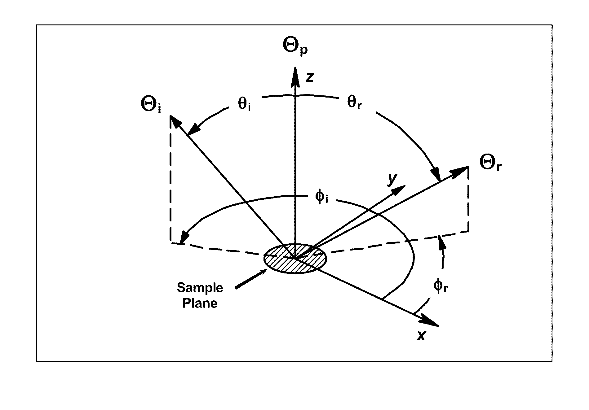
1) θi1=45 degrees, φi1=0 degrees, θs1=30 degrees, φs1=180 degrees

2) θi2=45 degrees, φi2=0 degrees, θs2=0 degrees, φs2=0 degrees

3) θi3=45 degrees, φi3=0 degrees, θs3=75 degrees, φs3=0 degrees

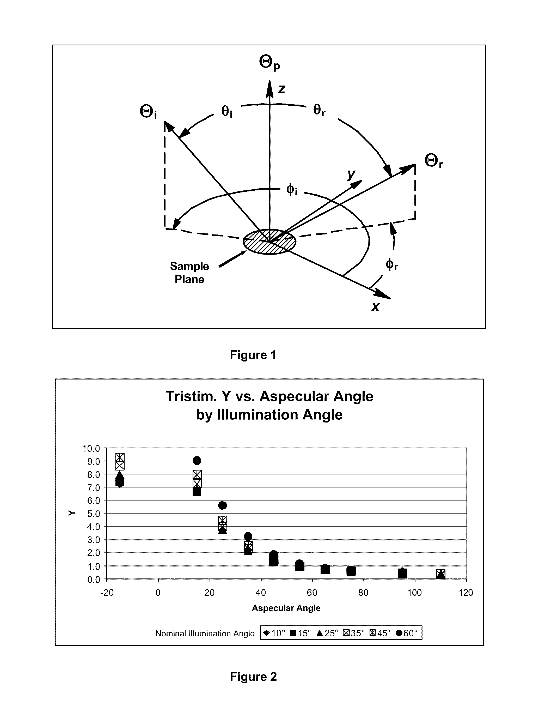
[0094]These geometries represent measurements at aspecular angles of 15 degrees, 45 degrees, and 110 degrees respectively. The L*a*b* mea...


PUM


Abstract

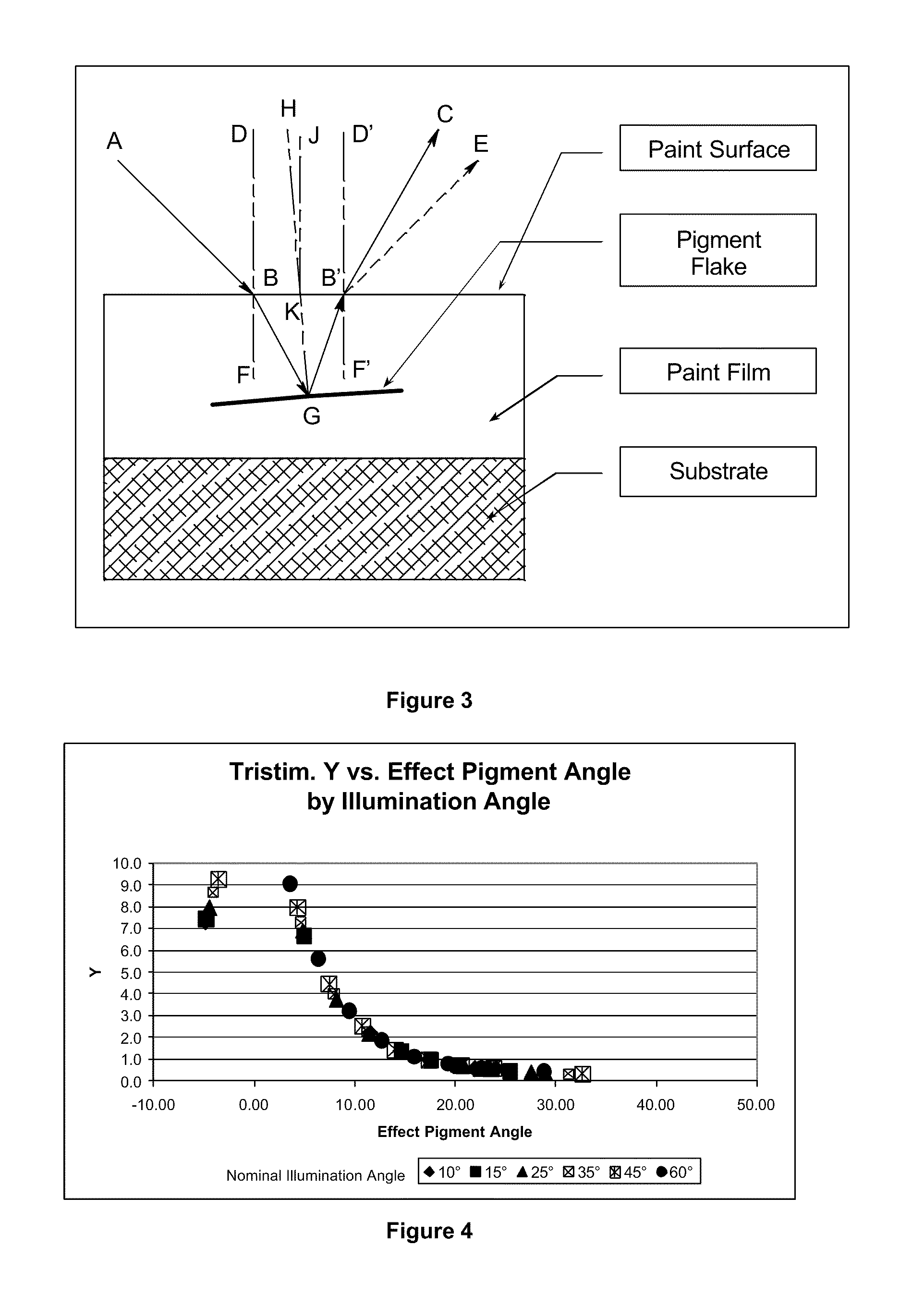
A computer-implemented process for generating a bidirectional reflectance distribution function (BRDF) of a gonioapparent material containing effect flake pigments in a solid medium using limited measurement data, comprising the following steps: (A) acquiring and inputting into a computing device (1) photometric data and (2) the refractive index of the solid medium of the gonioapparent material; (B) converting any non-linear photometric data from step A) above to linear photometric data; (C) using the illumination angle and the reflective scattering angle associated with the linear photometric data and the refractive index of the medium to calculate corresponding effect flake angles; (D) fitting the linear photometric data and the effect angle data with an equation; (E) calculating the corresponding effect flake angle needed to calculate the BRDF being generated in step (F); and (F) generating the BRDF from the corresponding effect flake angle from step (E) and the equation developed in step (D).

Description

FIELD OF THE INVENTION[0001]The present invention relates to a process for the generation of the bidirectional reflectance distribution function (BRDF) of gonioapparent materials or surfaces, specifically those containing effect flake pigments, such as, metallic flake pigments or special effect flake pigments that typically are hue shifting interference pigments, with limited measurement data.BACKGROUND OF THE INVENTION[0002]One the most general and well accepted means of describing the spectral and spatial reflective scattering properties of a material is by use of the bidirectional reflectance distribution function (BRDF). The BRDF is a fundamental description of the appearance of the surface of a material, and many other appearance attributes (such as, gloss, haze, and color) can be represented in terms of integrals of the BRDF over specific geometries and spectral conditions. Specification of the BRDF is critical to the marketability of consumer products, such as, automobiles, c...

Claims


Application Information

Patent Timeline
Patent Type & Authority Patents(United States)
IPC IPC(8): G06F17/10
CPCG01N21/4738G01N2021/4771
Inventor STEENHOEK, LARRY EUGENE
Owner AXALTA COATING SYST IP CO LLC
Learn More