
Locking device for a rail adjustment system

a locking device and adjustment system technology, applied in the direction of furniture parts, machine supports, other domestic objects, etc., can solve the problems of limited design freedom for the geometry configuration of the lower side of the seat, inconvenient installation, and inconvenient installation, so as to improve the effect of cost-effectiveness

Inactive Publication Date: 2011-07-19
BROSE FAHRZEUGTEILE GMBH & CO KG
View PDF25 Cites 80 Cited by
  • Summary
  • Abstract
  • Description
  • Claims
  • Application Information

AI Technical Summary

Benefits of technology

[0008]The invention is based on the object of providing a locking device for a rail adjustment system of a vehicle seat, which locking device is designed as a subassembly which is as compact as possible and which is connected to the rail adjustment system in as space-saving a manner as possible. Furthermore, a rail adjustment system is to be provided which is designed to be as space-saving as possible. Furthermore, a vehicle seat is to be provided which, with regard to the configuration of the seat geometry, is as improved and cost-effective as possible.
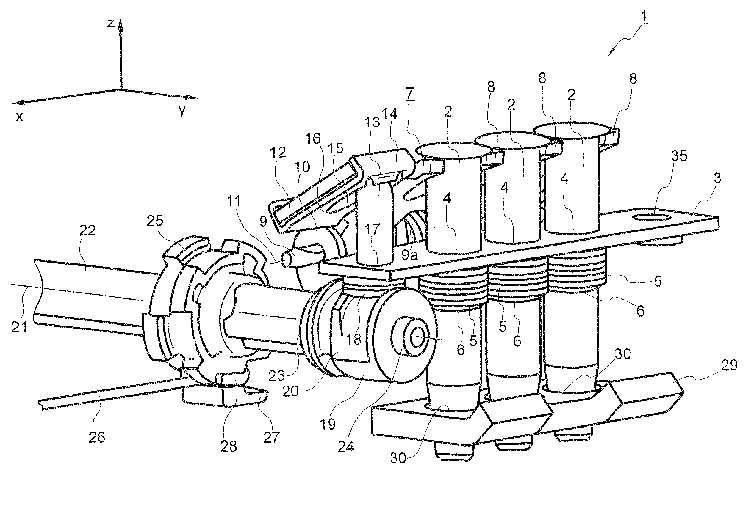
[0010]The invention is based on the consideration of being able to reduce the space required by the locking device essentially by entirely omitting the formation of a space-consuming surface of the lever element for the actuating introduction of force such that it is opposite the locking bolts, with respect to the pivot axis. This can be achieved in that the pivot axis is located in the lateral edge region of the lever element. The surface elements of the lever element, which elements serve to introduce and transmit force, are then formed on one and the same side with respect to the pivot axis. In particular, the adjusting surface which is set up for the actuating introduction of force to the lever element is therefore arranged, with respect to the pivot axis, on the same side as the locking bolt.
[0012]An application of force in the unlocking direction on the adjusting surface therefore brings about an unlocking pivoting movement of the lever element with the smallest possible construction volume for the locking device. This arrangement principle therefore permits the design of the locking device as a compact subassembly, the space requirement of which is essentially limited to a relatively close environment around the rails of the rail adjustment system assigned the locking device.
[0014]In particular, in an arrangement of this type, the unlocking pin is arranged parallel to the locking bolt, preferably essentially in the same position as the locking bolt with respect to the direction orthogonal to the unlocking direction and to the pivot axis. The extent of the locking device along this direction therefore remains restricted essentially to the region between the locking bolt and the intersecting point with the pivot axis, as a result of which the locking device can assume a particularly compact, space-saving form.
[0016]Furthermore, the adjusting surface is advantageously enclosed by a template for the end-side guidance of the unlocking pin. The template may be predetermined, for example, by means of a surface structure which can be placed onto the adjusting surface by means of a clip connection. Said surface structure has a fold with which the adjusting surface is gripped from behind on the rear side. In addition, it has a central cutout, with the cutout surface containing the entirety of contact points with the adjusting surface over the course of the pivoting movement of the unlocking pin and therefore the edge surface of the cutout forms a contour which guides and secures the unlocking pin.
[0017]The eccentric surface is appropriately formed on a rotational element, and the unlocking pin can be actuated by the eccentric surface by means of a rotational movement of the rotational element. The rotational movement of the rotational element is therefore converted into the linear movement of the unlocking pin by means of the eccentric surface. The distance of the eccentric surface from the axis of rotation of the rotational element therefore depends on the angle of rotation of the rotational element. The eccentric surface is preferably shaped such that it corresponds in the direction of the axis of rotation to the end side of the unlocking pin and is curved in the direction of rotation with a monotonously variable radius with respect to the axis of rotation. As a result, during a rotational movement of the rotational element, the unlocking pin is moved uniformly in the unlocking direction or locking direction. For this purpose, in a special configuration, the eccentric surface is bent in a worm-shaped manner such that, during a rotation of the rotational element through approximately 180°, the supporting surface of the unlocking pin is guided by the inside of the worm surface over the bent portion on the outside, or vice versa, with the unlocking pin being guided in the unlocking direction and being lowered in the locking direction. The rotational element is expediently designed as a single-piece plastic part. Different and, in particular, also complex surface geometries for the eccentric surface can therefore be produced in a simple manner, which is particularly cost-effective for production in large piece numbers.

Problems solved by technology

The surface of the lever element and the further means which are designed for introducing force to the surface are, overall, space-intensive.
If the locking device is arranged on the lower side of the seat, the surfaces engage in the region between the seat rails, as a result of which the construction space and the freedom of design for the configuration of the geometry on the lower side of the seat may be limited.

Method used


Image

  • Locking device for a rail adjustment system
  • Locking device for a rail adjustment system
  • Locking device for a rail adjustment system

Examples


Embodiment Construction

[0032]Mutually corresponding parts are provided with the same reference numbers in all of the figures.

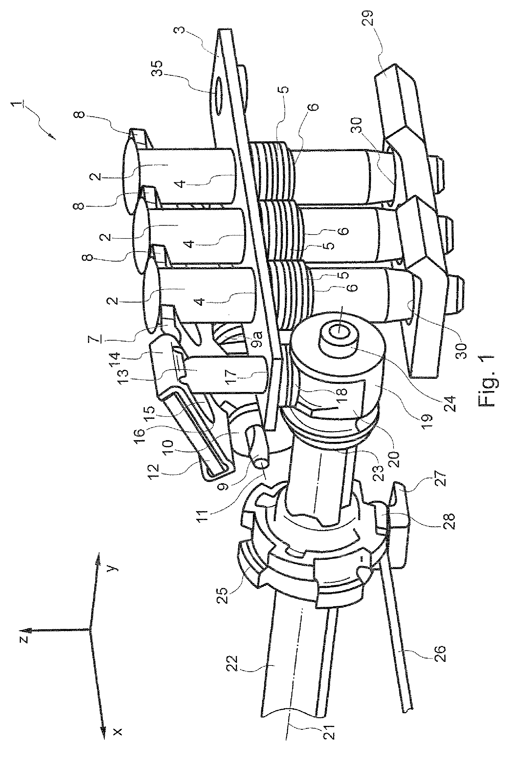
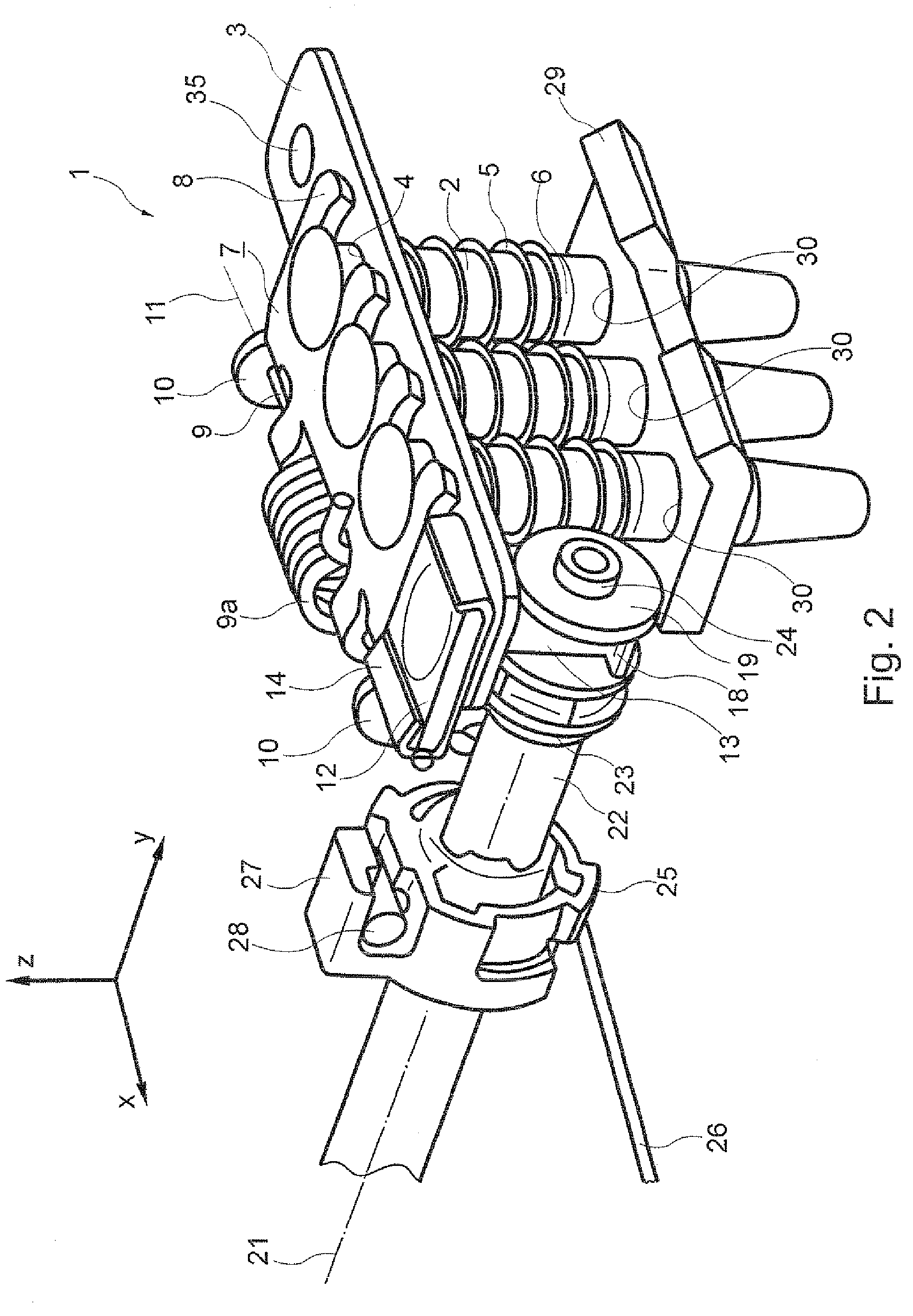
[0033]FIGS. 1 and 2 illustrate the locking device 1 in a laterally perspective view in an unlocked or in a locked state. The locking device 1 comprises three locking bolts 2 which are arranged one behind another and can be lowered in a vertical direction (inverse z direction) from an unlocked position (FIG. 1) into a locked position (FIG. 2). The locking bolts 2 pass through a supporting plate 3 and the upper rail of a rail adjustment system, on which the supporting plate 3 rests (compare FIGS. 5, 6), in bores 4 designed for this purpose. By means of prestressable spring elements, which engage around the locking bolts 2 and bear on the upper end side against the supporting plate 3 (compare FIGS. 3 and 4) and are clamped on the lower end side in a groove 6 of a respective locking bolt 2, a resetting force in the locking direction (inverse z direction) is built up on the locking bolts...


PUM


Abstract

A locking device for a rail adjustment system of a vehicle seat, with a number of locking bolts and with a lever element, which is pivotable about a pivoting axis, for unlocking the locking bolt is provided, wherein the locking bolts can be unlocked by an application of force to an adjusting surface of the lever element in the unlocking direction. Furthermore, a rail adjustment system is provided which comprises an upper rail which can be connected to a vehicle seat, a lower rail which can be mounted in a positionally fixed manner, an articulation shaft and a locking device of the type mentioned at the beginning.

Description

FIELD OF THE INVENTION[0001]The invention relates to a locking device for a rail adjustment system, furthermore to a rail adjustment system with a device of this type, and furthermore to a vehicle seat of a motor vehicle with a rail adjustment system of this type.BACKGROUND OF THE INVENTION[0002]A rail adjustment system for a vehicle seat usually comprises a lower rail which is mounted such that it is fixed on the vehicle, and an upper rail which is connected to the vehicle seat and is mounted in a linearly adjustable manner in relation to the lower rail. The vehicle seat can be positioned in the longitudinal direction of the vehicle therewith. The rail adjustment system is assigned a locking device by means of which the upper rail is locked to the lower rail in a desired longitudinal position of the vehicle seat.[0003]The locking device has to secure the vehicle seat in an adjusted longitudinal position, in particular under extreme applications of force that occur in a crash situat...

Claims


Application Information

Patent Timeline
Patent Type & Authority Patents(United States)
IPC IPC(8): F16M13/00
CPCB60N2/0806B60N2/0881
Inventor KOSTIN, SERGEJ
Owner BROSE FAHRZEUGTEILE GMBH & CO KG
Learn More