Apparatus and method for manipulating tissue
- Summary
- Abstract
- Description
- Claims
- Application Information
AI Technical Summary
Benefits of technology
Problems solved by technology
Method used
Image

Examples
first preferred embodiment
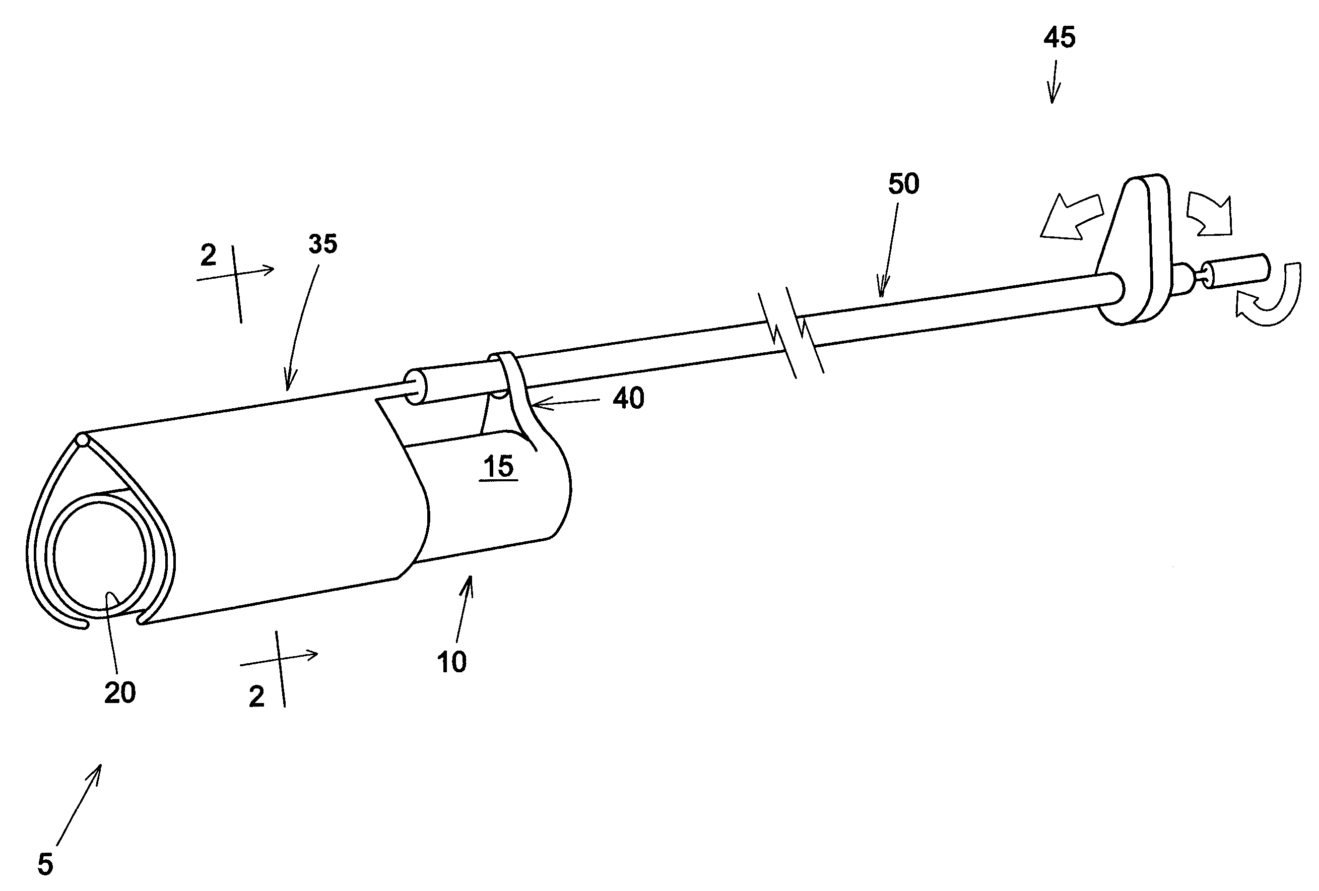
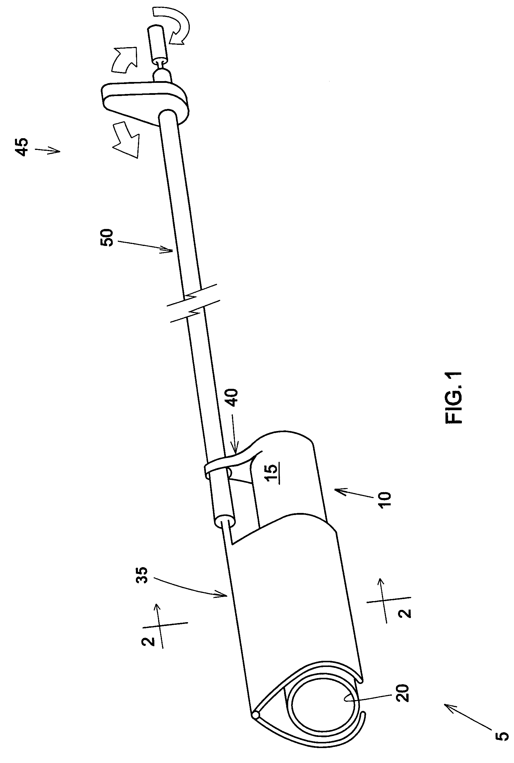
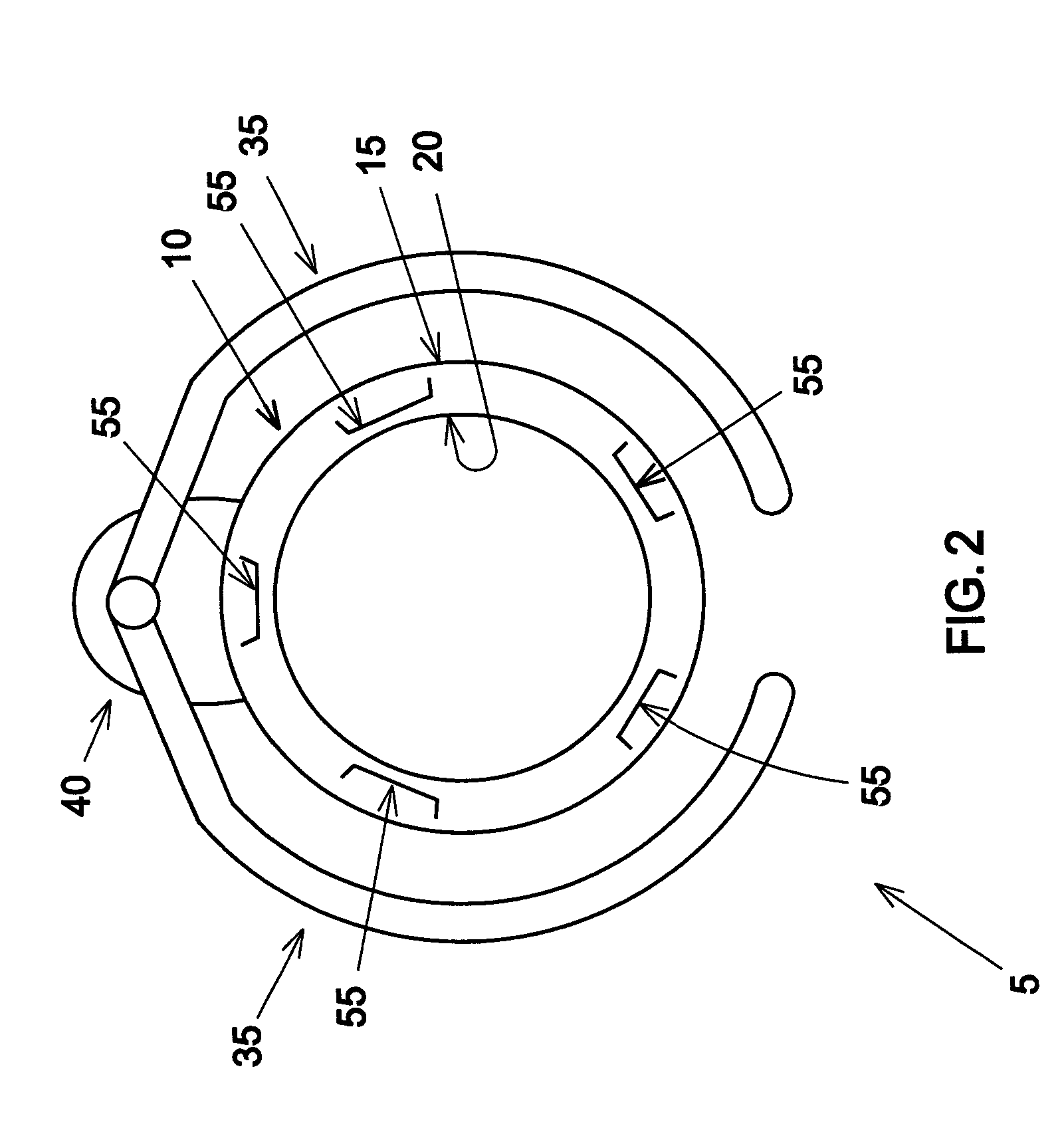
[0089]Looking now at FIGS. 1-4, in a first preferred embodiment of the present invention, an apparatus 5 comprises a flexible tube 10 having an outer surface 15 and an inner lumen 20. Various devices (e.g., working tools, scopes, etc.) can pass through inner lumen 20. Pods 25 (shown in FIGS. 3 and 4 but omitted from the remaining drawings for purposes of clarity) are provided in the outer surface 15 of flexible tube 10, whereby tissue may be drawn to the outer surface 15 of flexible tube 10. Conduits 30 (shown in FIGS. 3 and 4 but omitted from the remaining drawings for purposes of clarity) are formed in the side wall of flexible tube 10 and supply suction to pods 25.
[0090]Effector mechanisms 35 are configured to concentrically close about flexible tube 10. Preferably, effector mechanisms 35 are pivotally mounted to flexible tube 10 by a mount 40, with actuating mechanism 45 (preferably including a flexible tube 50) being used to position flexible tube 10 and effector mechanisms 35 ...
second preferred embodiment
[0097]Looking now at FIGS. 13-18, in a second preferred embodiment of the present invention, an apparatus 105 comprises a flexible shaft 110 with an actuator end 115 and an effector end 120. The effector end 120 has one or more effector mechanisms 125. The distal end of the device has a hollow tube 130 with a central lumen 135 (FIGS. 14 and 16). Objects such as a working instrument, endoscope, etc. can pass through the central lumen 135.
[0098]Effector mechanism 125 is adapted to open and close about an end pivot 140. A septum 145 has one portion anchored to effector mechanism 125 and another portion anchored to hollow tube 130. In one preferred construction, septum 145 enters the interior of effector mechanism 125 via a slot 150 (FIG. 16), and septum 145 enters the side wall of hollow tube 130 via a slot 155. The top portion of hollow tube 130, the underside of effector mechanism 125 and / or the septum 145 have suction pods 160 disposed therein, with suction being supplied to the suc...
third preferred embodiment
[0101]Looking now at FIGS. 25-29, in a third preferred embodiment of the present invention, an apparatus 205 comprises a flexible hollow tube 210 with an outer surface 215, an inner surface 220 and a central lumen 225. The sidewall 230 of flexible tube 210 may be solid, and / or the sidewall 230 of flexible tube 210 may be hollow through which other devices such as suction tubes, cables, wires, etc. may run.
[0102]Apparatus 205 includes an effector end 235 and an actuator end 240. The effector end 235 comprises a plurality of effector mechanisms 245. The effector mechanisms 245 can be parallel to but otherwise independent of one another (e.g., as a series of independent elements collectively forming the distal end of hollow tube 210) or one or more of the effector mechanisms 245 can be connected to one another (e.g., so as to form a slotted tube configuration, such as that shown in FIGS. 25, 28 and 29). Each of the effector mechanisms 245 is provided with one or more suction pods 250 (...
PUM
 Abstract
Description
Claims
Application Information
 - R&D
- Intellectual Property
- Life Sciences
- Materials
- Tech Scout
- Unparalleled Data Quality
- Higher Quality Content
- 60% Fewer Hallucinations
Browse by: Latest US Patents, China's latest patents, Technical Efficacy Thesaurus, Application Domain, Technology Topic, Popular Technical Reports.
© 2025 PatSnap. All rights reserved.Legal|Privacy policy|Modern Slavery Act Transparency Statement|Sitemap|About US| Contact US: help@patsnap.com