Support for assembly with flat panel video monitors, coupler for attachment of the support to an extension arm, and assembly methods

a technology for video monitors and support brackets, applied in the direction of support brackets, furniture parts, machine supports, etc., can solve the problems of difficult use, relative complex devices, and difficult assembly

Inactive Publication Date: 2011-02-01
DENTAL EQUIP
View PDF6 Cites 5 Cited by
  • Summary
  • Abstract
  • Description
  • Claims
  • Application Information

AI Technical Summary

Benefits of technology

According to another aspect, a coupler of the present invention may provide for movement of a flat panel video monitor about two axes of rotation. A first axis of rotation extends through the coupler itself and, depending upon the orientation of a hinge that is held in place by the coupler, may provide for side-to-side tilting of the video monitor relative to the coupler, or for top-to-bottom tilting of the video monitor. A second axis is defined by a joint between the coupler and an extension arm, in which the joint may be configured to rotate relative to an end of the extension arm. In some embodiments, in which the joint comprises a substantially linear element, rotation of the joint relative to the end of the extension arm (e.g., by grasping one or both handles of a support for a flat panel video monitor) may provide for rotation of the flat panel video monitor about a fixed axis, such as when a change between a portrait and landscape orientation of the monitor is desired. In other embodiments, in which the joint between the coupler and the extension arm is bent (e.g., at an angle of about 45°, about 90°, etc.), rotation of the joint relative to the extension arm may provide for wider, swinging movement of a flat panel video monitor along an arc, rather than about a fixed axis.

Problems solved by technology

While some state-of-the art support assemblies enable movement of monitors to a large number of locations and orientations, they are relatively complex devices that are difficult to assemble, and sometimes difficult to use.

Method used


Image

  • Support for assembly with flat panel video monitors, coupler for attachment of the support to an extension arm, and assembly methods
  • Support for assembly with flat panel video monitors, coupler for attachment of the support to an extension arm, and assembly methods
  • Support for assembly with flat panel video monitors, coupler for attachment of the support to an extension arm, and assembly methods

Examples


Embodiment Construction

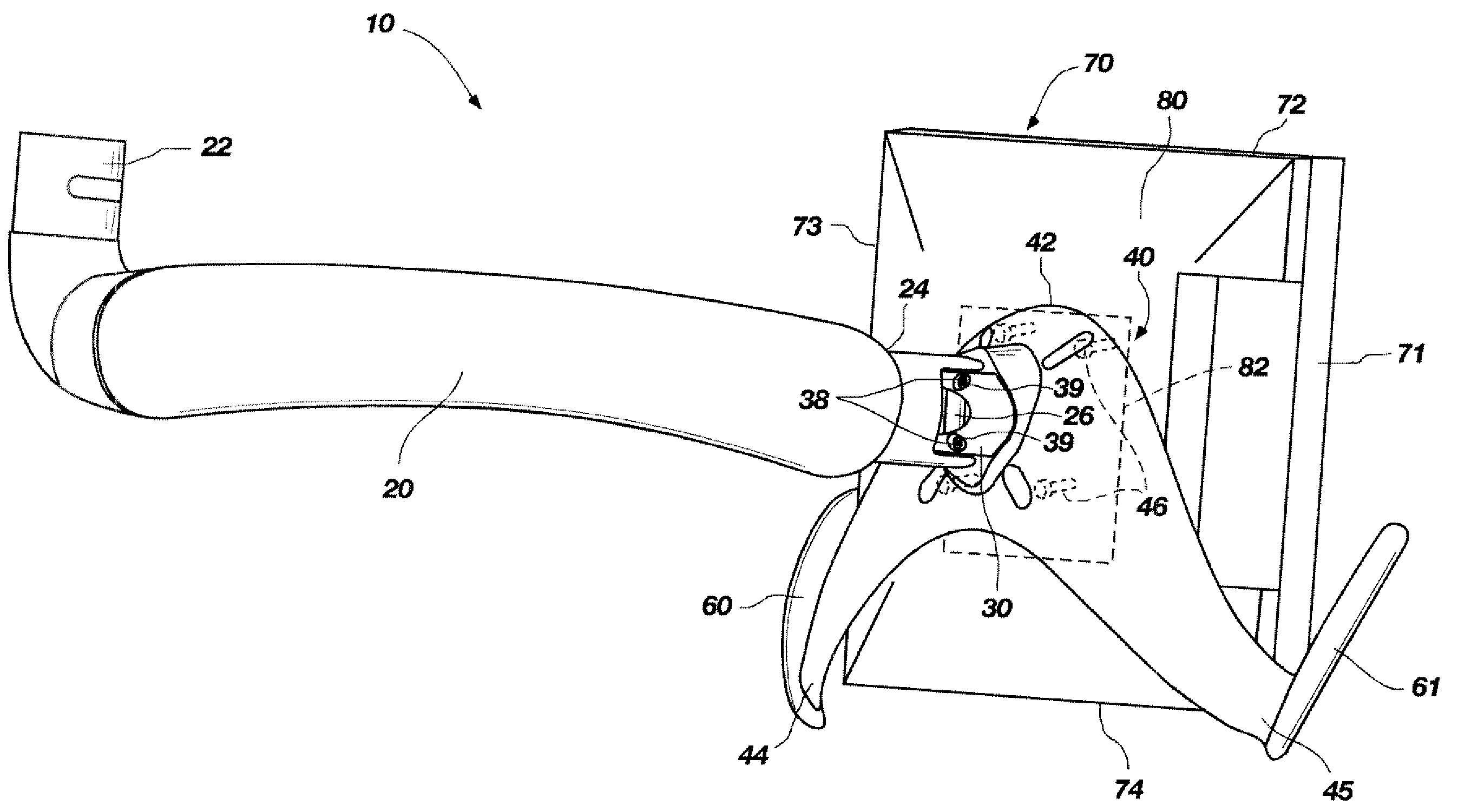
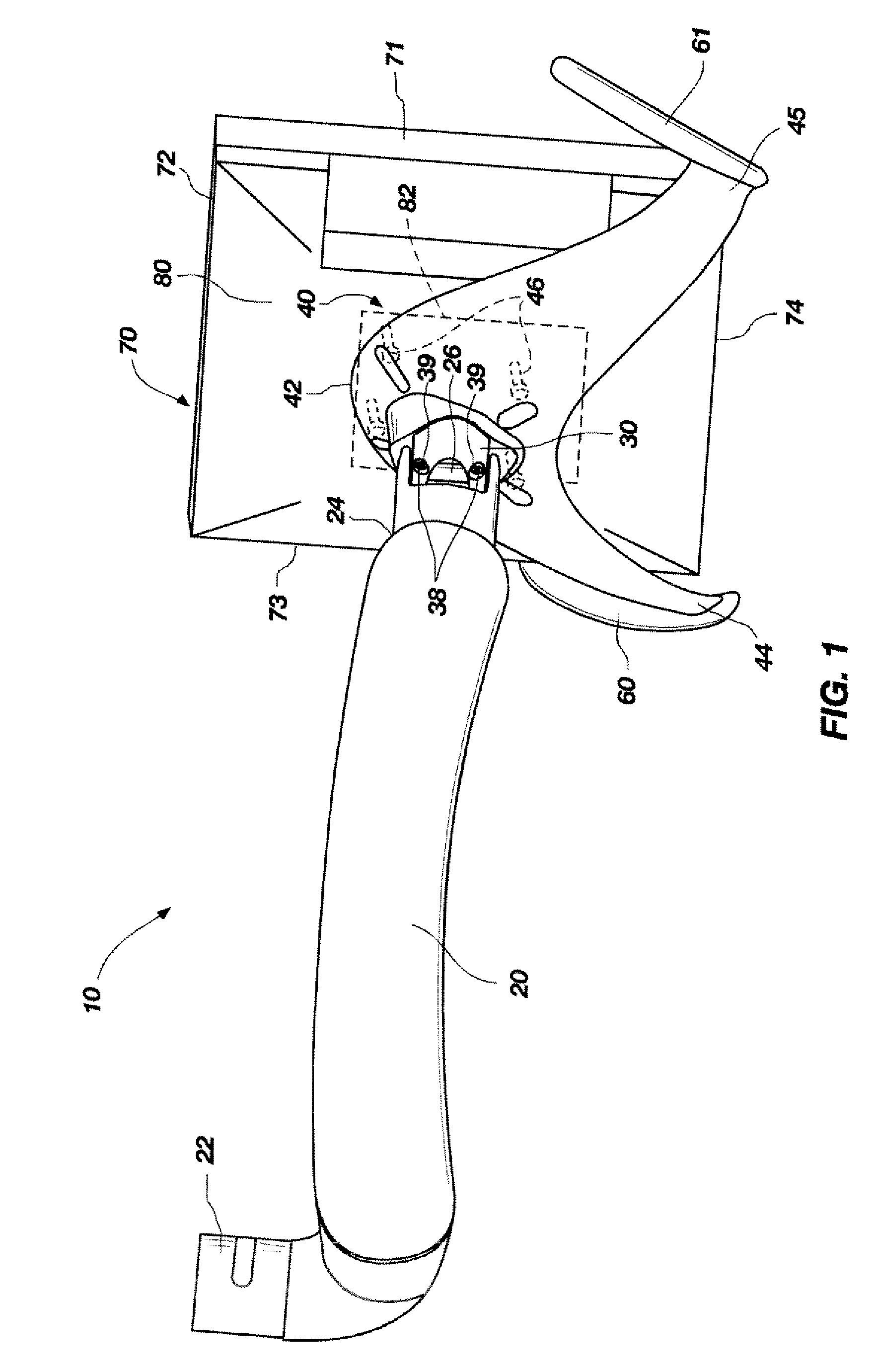
Referring to FIG. 1, a portion of a support assembly 10 for a flat panel video monitor 70 is illustrated. Support assembly 10 includes a support 40 for carrying flat panel video monitor 70, a coupler 30 secured to support 40, and an extension arm 20 secured or associated with coupler 30.

In the illustrated embodiment, extension arm 20 is an elongate element that includes a first end 22 and an opposite second end 24. First end 22 is configured to be secured to a mount (not shown), which may be secured in a fixed position to a desired location, such as a countertop, wall, ceiling, or other suitable location. Coupler 30 is connected to second end 24 of extension arm 20.

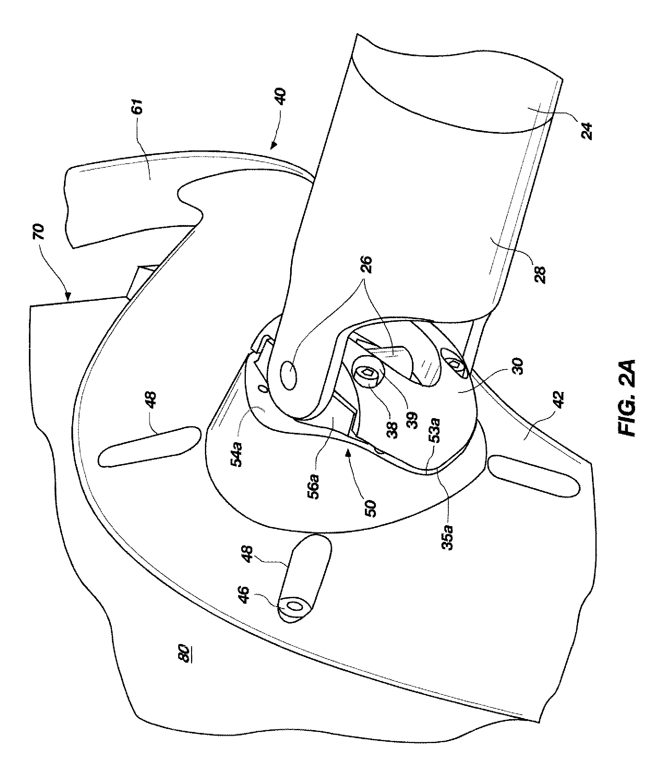
With continued reference to FIG. 1, as well as to FIGS. 2A through 3, coupler 30 may be connected to second end 24 of extension arm 20 in any suitable manner known in the art. The connection between coupler 30 and second end 24 may be rigidly fixed, or it may provide for movement about one or more axes. FIG. 1 shows an em...


PUM


Abstract

A unitary support for a flat panel video monitor includes a yoke that may be attached to a back side of the monitor in two or more different orientations, and handles extending from opposite side ends of the yoke. The handles may extend diagonally from the side ends of the yoke, imparting the support with a general appearance of the letter “W.” The yoke is also configured to be secured directly to a coupler at the end of an extension arm. A coupler attachment element of the yoke and a support attachment element of the coupler may have engagement features that are configured complementarily to each other to prevent undesired movement of the support relative to the coupler and the extension arm. The complementary engagement features may also enable attachment of the coupler to the support in two or more discrete orientations.

Description

FIELD OF INVENTIONThe present invention relates generally to apparatus for supporting flat panel video monitors, such as computer monitors and televisions. More specifically, the present invention relates to supports and couplers that are parts of support assemblies for flat panel video monitors, which enable users to readily position flat panel video monitors at a plurality of locations.BACKGROUND OF RELATED ARTA variety of apparatus have been developed to support flat panel video monitors. Among these apparatus are assemblies that facilitate movement of flat panel video monitors to a large number of locations, sometimes in different orientations. Such assemblies have found increased use in a number of settings, including operating rooms, dental offices, and doctor offices, where ready movement of a monitor is desirable, particularly since the individuals (e.g., hygienist, dentist, patient, etc.) who may need to view the monitor may be present in different locations throughout a ro...

Claims


Application Information

Patent Timeline
Patent Type & Authority Patents(United States)
IPC IPC(8): E04G3/00
CPCF16M11/10F16M11/12F16M11/2071F16M13/02F16M13/027Y10S248/919Y10S248/921
Inventor UNSWORTH, AUSTIN EVERETTDECARR, GARYHEMMER, NATHAN
Owner DENTAL EQUIP
Why Eureka
Try Eureka