
Approach for reducing overheating of direct injection fuel injectors

a fuel injector and fuel injection technology, which is applied in the direction of electrical control, process and machine control, etc., can solve the problems of degradation little or no fuel supplied to etc., and achieves the effects of reducing overheating of the direct injection fuel injector, reducing overheating, and reducing overheating

Inactive Publication Date: 2011-01-11
FORD GLOBAL TECH LLC
View PDF12 Cites 33 Cited by
  • Summary
  • Abstract
  • Description
  • Claims
  • Application Information

AI Technical Summary

Benefits of technology

The patent text describes a method for controlling fuel supplied to an engine of a vehicle to improve fuel economy performance and operating efficiency. The method involves selectively supplying fuel to direct injection fuel injectors and port injection fuel injectors based on the amount of fuel in the fuel storage tanks. This approach helps to prevent overheating of the direct injection fuel injectors and allows for stable combustion resulting in improved fuel economy performance under various operating conditions. Additionally, the method allows for adjustment of fuel injection to optimize engine performance under different operating conditions.

Problems solved by technology

In particular, in the above engine configuration, if the fuel storage tank that supplies ethanol to the direct injection fuel injectors becomes empty, or too low, then little or no fuel is supplied to the direct injection fuel injectors.
Over time, the direct injection fuel injectors may become overheated due to a lack of fuel flowing through the direct injection fuel injectors potentially resulting in degradation of the direct injection fuel injectors.

Method used


Image

  • Approach for reducing overheating of direct injection fuel injectors
  • Approach for reducing overheating of direct injection fuel injectors
  • Approach for reducing overheating of direct injection fuel injectors

Examples


Embodiment Construction

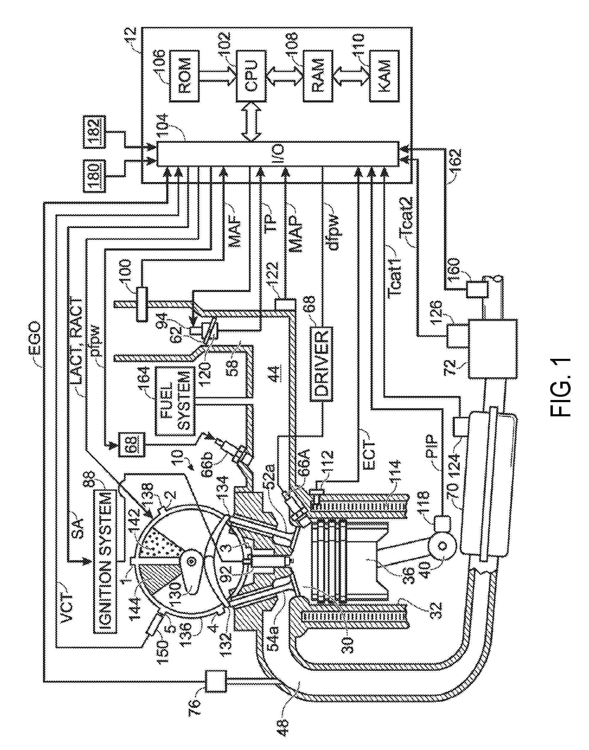
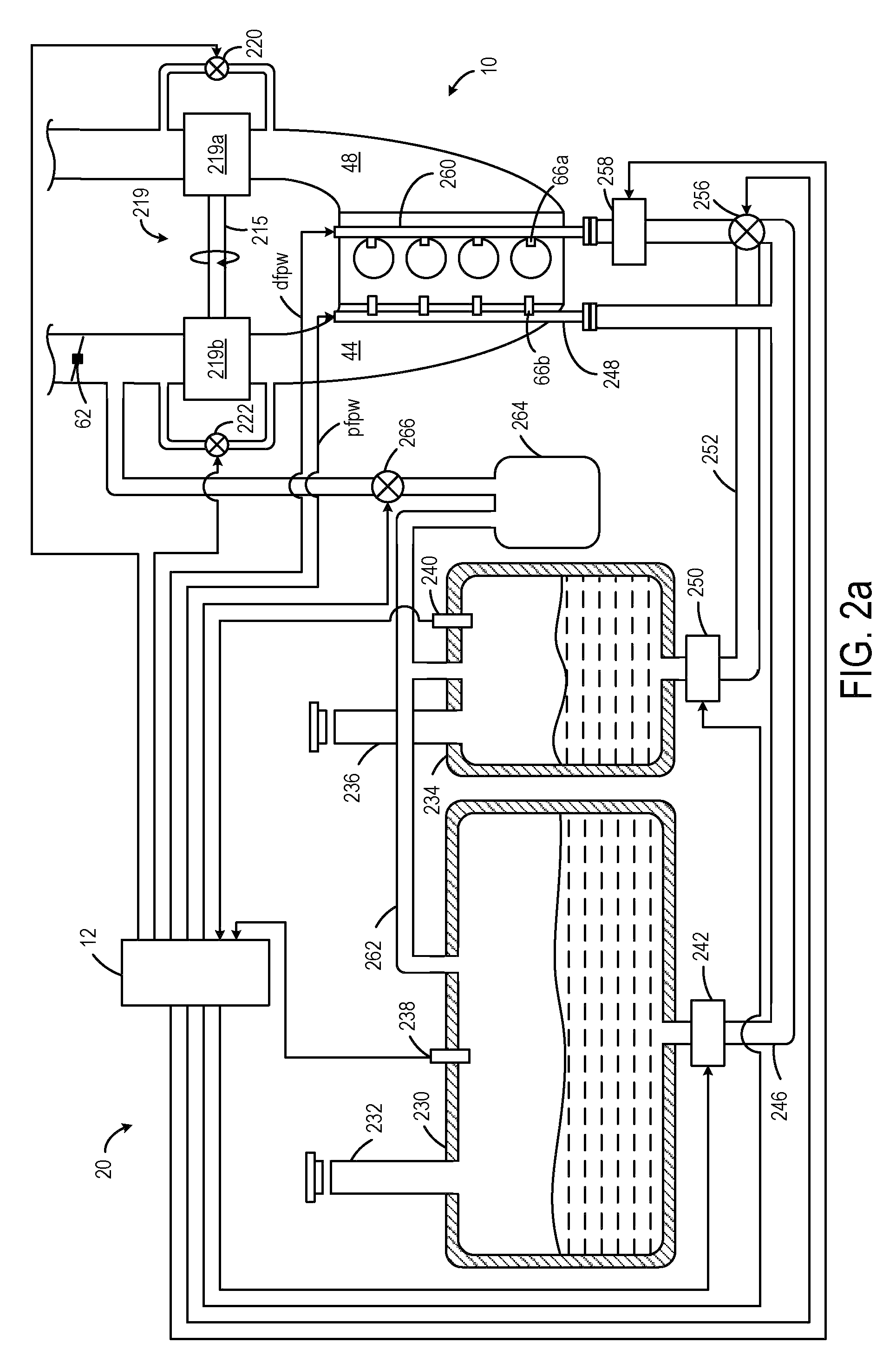
[0014]FIG. 1 shows one cylinder of a multi-cylinder engine, as well as the intake and exhaust path connected to that cylinder. In the embodiment shown in FIG. 1, engine 10 is capable of using two different fuels, and / or two different injectors in one example. For example, engine 10 may use gasoline and an alcohol containing fuel such as ethanol, methanol, a mixture of gasoline and ethanol (e.g., E85 which is approximately 85% ethanol and 15% gasoline), a mixture of gasoline and methanol (e.g., M85 which is approximately 85% methanol and 15% gasoline), etc. In another example, two fuel systems are used, but each uses the same fuel, such as gasoline. In still another embodiment, a single injector (such as a direct injector) may be used to inject a mixture of gasoline and an alcohol based fuel, where the ratio of the two fuel quantities in the mixture may be adjusted by controller 12 via a mixing valve, for example. In still another example, two different injectors for each cylinder ar...


PUM


Abstract

A method of controlling fuel supplied to an engine is provided. The engine includes at least one cylinder having a port injection fuel injector being supplied with fuel from at least one of a first fuel storage tank and a second fuel storage tank and a direct injection fuel injector being selectively supplied with fuel from one of the first fuel storage tank and the second fuel storage tank. The method includes at a first condition, supplying at least some of a second type of fuel from the second fuel storage tank to the direct injection fuel injector and supplying at least some of a first type of fuel from the first fuel storage tank to the port injection fuel injector, and at a second condition, supplying at least some of the first type of fuel from the first fuel storage tank to the direct injection fuel injector.

Description

BACKGROUND AND SUMMARY[0001]An engine of a vehicle may include cylinders having a direct injection fuel injector and a port injection fuel injector. The port injection fuel injector may be supplied with gasoline only from a first fuel storage tank and the direct injection fuel injector may be supplied with ethanol only from a second fuel storage tank. This engine configuration is one example of what may be referred to as an “ethanol boosted system” or EBS. This engine configuration may enhance engine operating efficiency and improve fuel economy performance. For example, under increased torque demand conditions, the port injection fuel injector may inject a reduced amount of gasoline and the direct injection fuel injector may inject ethanol to abate engine knock which otherwise would be caused by the increased torque.[0002]The inventors herein have recognized issues with the above approach. In particular, in the above engine configuration, if the fuel storage tank that supplies etha...

Claims


Application Information

Patent Timeline
Patent Type & Authority Patents(United States)
IPC IPC(8): G06F19/00F02B17/00F02B7/04F02M43/00
CPCF02D19/081F02D41/0025F02D41/3094F02M25/089F02D19/061F02D19/0621F02D19/0665F02D19/0671F02D19/0689F02D19/0694F02D19/084F02B1/12F02D41/3023Y02T10/36F02D19/0628F02D19/0692Y02T10/30
Inventor STEIN, ROBERT ALBERTBYRD, KEVIN DURAND
Owner FORD GLOBAL TECH LLC
Learn More