Amphibious vehicle which has elements for forming a floating bridge

a technology of floating bridges and amphibious vehicles, which is applied in the direction of bridges, propulsive elements, vessel construction, etc., can solve the disadvantage of having to turn the group of elements into a single unit, and achieve the effect of increasing the stepping down effect of the load of deploymen

Inactive Publication Date: 2010-04-06
CONSTR NAVALES & IND DE LA MEDITERRANEE CNIM
View PDF7 Cites 7 Cited by
  • Summary
  • Abstract
  • Description
  • Claims
  • Application Information

AI Technical Summary

Benefits of technology

[0010]Thanks to these arrangements, the vehicles of the invention are distinguished by a versatile loading capacity, particularly for use in ferry mode, which allows the crossing of vehicles of medium class (for example, military load class MLC35) with one module, of heavy tank class (for example, MSC70) with two modules, and up to heavy wheeled vehicle class (for example, MLC100) with three modules. Furthermore, the vehicle of the invention is distinguished by its ability to form a bridge making it possible to cover gap widths starting from 23 meters, by the complete automation of the deployment operations and the very extensive automation of the operations for connection between vehicles, as well as by the small space requirement and weight making air transport by means of medium capacity aircraft possible.
[0058]the vehicle includes some second locking means making it possible to lock it with another vehicle of the same design during the production of a ferry or a bridge, the second locking means being configured so as to allow locking between two vehicles regardless of the deployment configuration of each of the vehicles;

Problems solved by technology

In this sense, it has proven disadvantageous to have to turn the group of elements in the form of a single unit.

Method used


Image

  • Amphibious vehicle which has elements for forming a floating bridge
  • Amphibious vehicle which has elements for forming a floating bridge
  • Amphibious vehicle which has elements for forming a floating bridge

Examples


Embodiment Construction

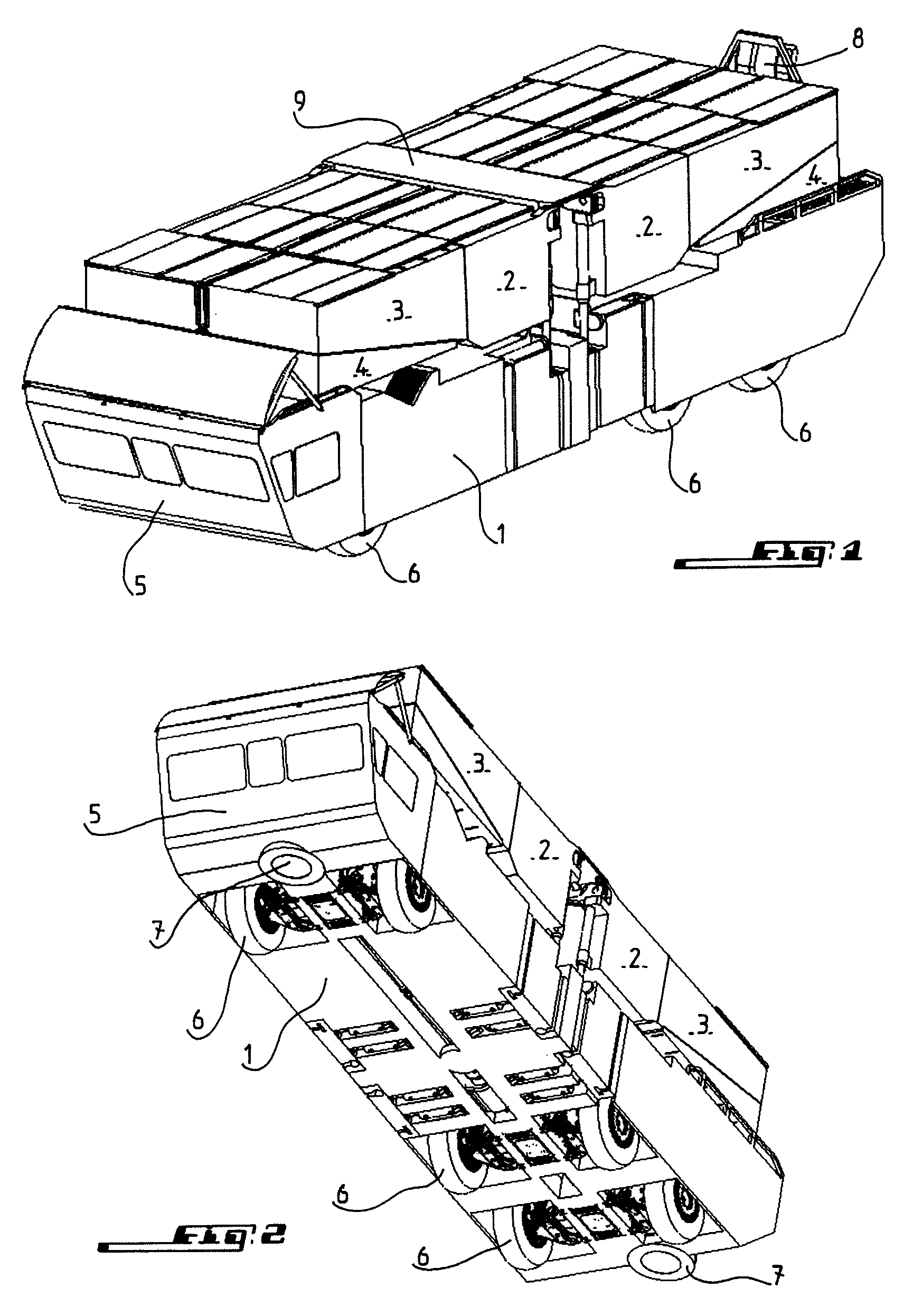
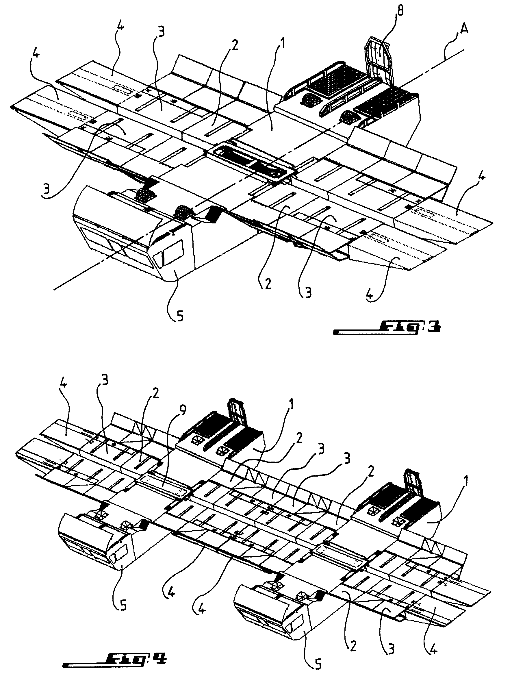
[0093]As shown by FIGS. 1 and 2 respectively in the form of a perspective view from above and in the form of a perspective view from below, an amphibious vehicle according to the invention has, arranged on self-propelled rolling base 1, elements such as caissons 2, floats 3 and ramps 4, these elements being arranged some at least partially over the others and according to an orientation essentially parallel to longitudinal axis A of rolling base 1, when the vehicle is in a folded up configuration for movement on land. The elements are configured so that they can be deployed in such a way as to form a track or bridge portion oriented transversely with respect to longitudinal axis A of rolling base 1, when the vehicle, alone or with another vehicle of the same design, is supposed to form a floating bridge or a ferry.

[0094]The main structure of rolling base 1 of the vehicle of the invention consists of a sealed self-supporting body preferably made of aluminum and a cabin connected with...


PUM


Abstract

An amphibious vehicle which has elements, such as caissons, floats, and ramps, arranged on a self-propelled rolling base, oriented essentially parallel to a longitudinal axis of the rolling base, when the vehicle is in a folded configuration for movement on land, and which are deployed to form a track or bridge portion oriented transversely with respect to the longitudinal axis of the rolling base, when the vehicle, alone or with another vehicle of the same design, is used to form a floating bridge or ferry. The vehicle has a deployment device for deploying elements by pivoting of four groups of the elements around four vertical shafts spaced from one another, according to at least three different configurations, each group of elements including at least one caisson.

Description

FIELD OF THE INVENTION[0001]The present invention relates to an amphibious vehicle which has elements such as caissons, floats and ramps for forming a floating bridge.[0002]The vehicle of the invention forms part of the systems for crossing wet gaps for heavy vehicles, which are integrated in an amphibious vehicle authorized for road transport as well as river transport.BACKGROUND[0003]Crossing wet or dry gaps being principally but not exclusively one of the main fields of activity of military engineering, the present invention will mainly concern the construction of military amphibious vehicles which need to be configured so as to be capable of enabling the crossing of vehicles, particularly heavy military vehicles, for example, up to 110 metric tons, but also personnel with their equipment. Furthermore, it is desirable for the vehicle equipped with the invention to be transportable by air so that it can be moved quickly from one region to another, at least by airplane and preferab...

Claims


Application Information

Patent Timeline
Patent Type & Authority Patents(United States)
IPC IPC(8): B60F3/00E01D15/14E01D15/20E01D15/22
CPCE01D15/22B60F3/0061
Inventor RICHEUX, ELISABETHAUBERT, HENRI
Owner CONSTR NAVALES & IND DE LA MEDITERRANEE CNIM
Why Eureka
Try Eureka