
Knee brace hinges with adaptive motion

a technology of adaptive motion and hinges, applied in the field of orthopaedic braces, can solve the problems of prone to modification of knee brace hinges, and achieve the effect of improving the stability and stability of the knee bra

Active Publication Date: 2009-11-10
DJO
View PDF80 Cites 5 Cited by
  • Summary
  • Abstract
  • Description
  • Claims
  • Application Information

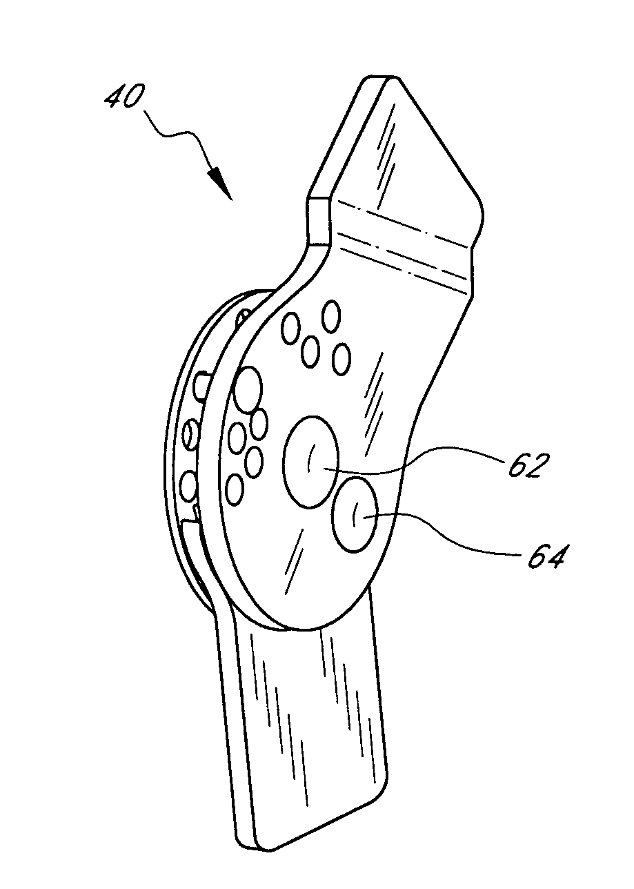
AI Technical Summary

Benefits of technology

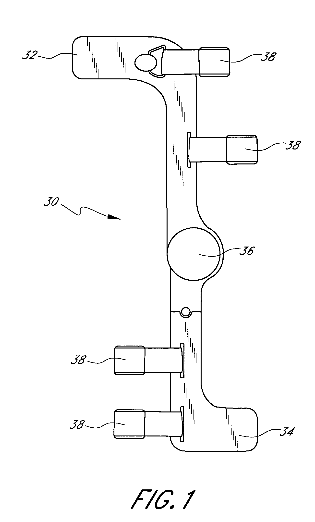
[0010]The preferred embodiments of the present knee brace hinges with adaptive motion have several features, no single one of which is solely responsible for their desirable attributes. Without limiting the scope of these knee brace hinges as expressed by the claims that follow, their more prominent features will now be discussed briefly. After considering this discussion, and particularly after reading the section entitled “Detailed Description of the Preferred Embodiments,” one will understand how the features of the preferred embodiments provide advantages, which include the ability to track natural knee motion so as to avoid applying undesired forces to the knee, while at the same time restraining the knee against harmful motions.
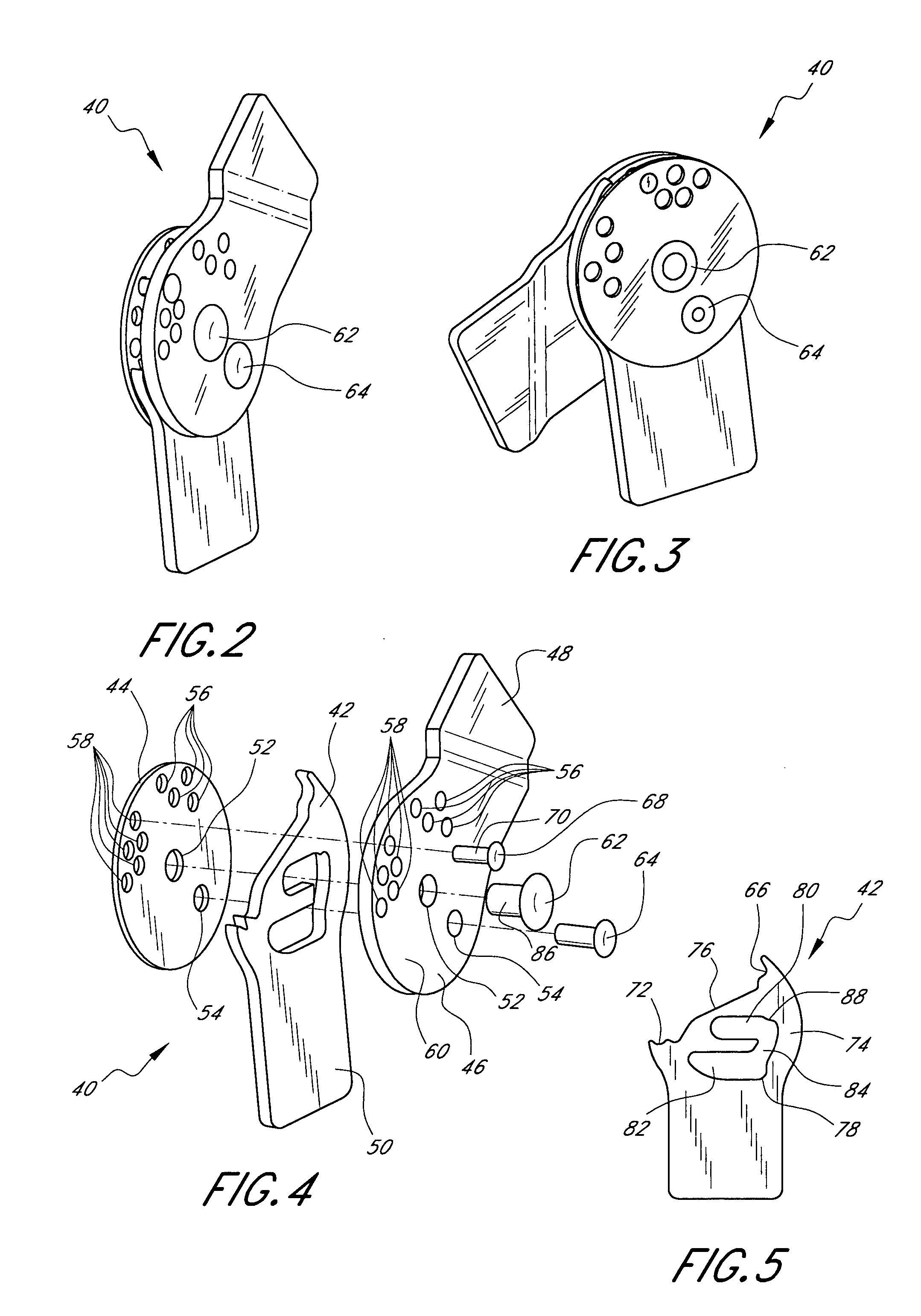
[0013]Another embodiment of the present knee brace hinges comprises at least a first hinge plate including a pivot aperture and a first cam slot, a cam plate including a second cam slot, the cam plate being secured to the hinge plate, a pivot member extending through the pivot aperture and the second cam slot, and a guide member secured to the cam plate and extending into the first cam slot. Interaction of the pivot member with the second cam slot and interaction of the guide member with the first cam slot controls rotational and translational movement of the hinge plate and cam plate with respect to one another.
[0014]Another embodiment of the present knee brace hinges comprises at least a first hinge plate, a cam plate including a cam slot shaped substantially as a diamond with rounded corners, the cam plate being secured to the hinge plate, and a guide member shaped substantially as an oval secured to the hinge plate and extending into the cam slot. Interaction of the guide member with the cam slot controls rotational and translational movement of the hinge plate and cam plate with respect to one another.

Problems solved by technology

These knee brace hinges are, however, susceptible to modifications and alternate constructions from that discussed above that are fully equivalent.

Method used


Image

  • Knee brace hinges with adaptive motion
  • Knee brace hinges with adaptive motion
  • Knee brace hinges with adaptive motion

Examples


Embodiment Construction

,” one will understand how the features of the preferred embodiments provide advantages, which include the ability to track natural knee motion so as to avoid applying undesired forces to the knee, while at the same time restraining the knee against harmful motions.

[0011]One embodiment of the present knee brace hinges comprises at least a first hinge plate and a cam plate. The hinge plate and the cam plate are secured to one another such that in a first range of motion the hinge plate is pivotable with respect to the cam plate but not translatable with respect thereto, and in a second range of motion the hinge plate is pivotable and translatable with respect to the cam plate.

[0012]Another embodiment of the present knee brace hinges comprises at least a first hinge plate including a pivot aperture and a guide aperture, a cam plate including a cam slot, the cam plate being secured to the hinge plate, a pivot member extending through the pivot aperture and the cam slot, and a guide mem...


PUM


Abstract

The disclosed knee brace hinges enable a knee brace including the hinges to track the natural motion of the brace wearer's knee while restraining the knee from harmful motions. In certain embodiments, in a first range of motion the hinges have only one degree of freedom, rotation about a fixed axis. In a second range of motion, the hinges have at least two degrees of freedom, rotation and translation.

Description

RELATED APPLICATION[0001]This application claims priority to provisional application Ser. No. 60 / 534,719, filed on Jan. 7, 2004, the entire contents of which are hereby expressly incorporated by reference.BACKGROUND OF THE INVENTION[0002]1. Field of the Invention[0003]The present invention relates to orthopedic braces.[0004]2. Description of the Related Art[0005]Many knee braces restrain the wearer's knee against harmful motions. Many of these knee braces provide such restraint while at the same time guiding the wearer's knee along a natural range of motion. Accordingly, many knee brace hinges attempt to mimic the natural motion of the knee. Some of these designs include monocentric hinges, polycentric hinges, four-bar-linkage hinges, and cam hinges. Each of these designs has a unique range of motion.[0006]In general, when viewed in the sagittal plane, the human knee moves in a slide-and-glide fashion in which the femur partially rolls back posteriorly on the tibia as the knee flexe...

Claims


Application Information

Patent Timeline
Patent Type & Authority Patents(United States)
IPC IPC(8): A61F5/00A61F5/01
CPCA61F5/0123A61F5/0125A61F2005/0148
Inventor NATHANSON, JEREMY J.
Owner DJO
Learn More