
Fiber optic cables and assemblies for fiber toward the subscriber applications

a fiber optic cable and subscriber technology, applied in the direction of optics, fibre mechanical structures, instruments, etc., can solve the problems of high optical attenuation, fiber optic cable encountering rough terrain, and complex problems for craft, service provider, and manufacturer

Active Publication Date: 2009-07-28
CORNING OPTICAL COMM LLC
View PDF43 Cites 77 Cited by
  • Summary
  • Abstract
  • Description
  • Claims
  • Application Information

AI Technical Summary

Problems solved by technology

Pressure clamp 19 can not be used with all fiber optic cable designs since it may cause damage and / or elevated levels of optical attenuation.
For instance, the fiber optic cable can encounter rough terrain such as being pushed against rocks, or the like or rough handling during installation such as pulling into a duct.
Because this excess length for slack storage can take a substantial amount of space, may look unsightly, and / or there may be a limited space available, the craft, generally speaking, selects a length of preconnectorized fiber optic cable from his inventory that minimizes the length for slack storage for the particular installation.
For instance, the craft may carry up to fifteen different lengths of preconnectorized fiber optic cables into the field, which creates complexity issues for the craft, the service provider, and the manufacturer.

Method used


Image

  • Fiber optic cables and assemblies for fiber toward the subscriber applications
  • Fiber optic cables and assemblies for fiber toward the subscriber applications
  • Fiber optic cables and assemblies for fiber toward the subscriber applications

Examples


Embodiment Construction

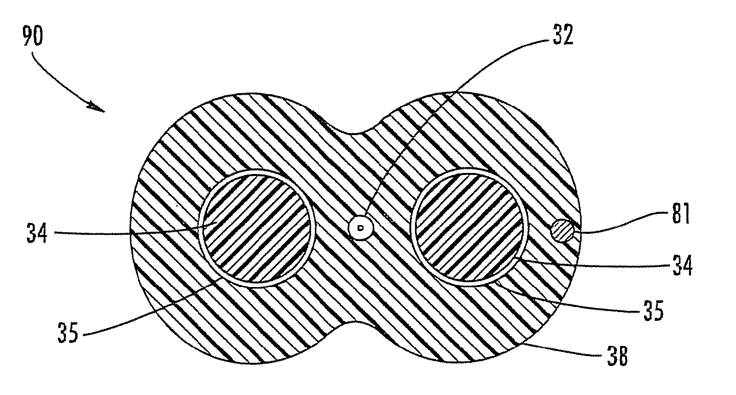
[0031]Reference will now be made in detail to the present preferred embodiments of the invention, examples of which are illustrated in the accompanying drawings. When practical, the same reference numerals will be used throughout the drawings to refer to the same or like parts. FIG. 3 is a cross-sectional view of a fiber optic cable 30 having at least one optical fiber 32, a first and a second strength component 34, and a cable jacket 38. First and second strength components 34 are disposed on opposite sides of optical fiber 32 and generally aligned along a common plane A-A, thereby providing a preferential bend characteristic to fiber optic cable 30. As depicted, cable jacket 38 contacts the optical fiber 32 and first and second strength members 34. Cable jacket 38 has a medial height MH disposed about optical fiber 32 that is less than an end height EH of fiber optic cable 30, which is advantageous for preserving optical performance during clamping within pressure clamp 19 as disc...


PUM


Abstract

Disclosed are fiber optic cables and assemblies for routing optical networks closer to the subscriber. The fiber optic cables have a robust design that is versatile by allowing use in aerial application with a pressure clamp along with use in buried and / or duct applications. Additionally, the fiber optic cables and assemblies have a relatively large slack storage capacity for excess length. Assemblies include hardened connectors and / or optical connectors such as plugs and / or receptacles suitable for outdoor plant applications attached to one or more ends of the fiber optic cables for plug and play connectivity.

Description

RELATED APPLICATIONS[0001]The present application is a Continuation-in-Part of U.S. patent application Ser. No. 11 / 986,705 filed on Nov. 26, 2007, now U.S. Pat. No. 7,539,380 the disclosure of which is incorporated herein by reference.BACKGROUND[0002]1. Field of the Disclosure[0003]The present invention relates to fiber optic cables and assemblies suitable fiber optic networks such as fiber to the subscriber or fiber to the node applications. More particularly, the present invention relates generally to fiber optic cables having a robust design with a relatively large slack storage capacity for excess length along with associated assemblies for plug and play connectivity.[0004]2. Technical Background[0005]Communications networks are used to transport a variety of signals such as voice, video, data and the like to subscribers. Service providers are routing optical fiber deeper into communication networks, thereby increasing the bandwidth available to subscribers for receiving the des...

Claims


Application Information

Patent Timeline
Patent Type & Authority Patents(United States)
IPC IPC(8): G02B6/44
CPCG02B6/381G02B6/4433G02B6/3865G02B6/3869G02B6/447G02B6/4403G02B6/387G02B6/562
Inventor ABERNATHY, GEORGE C.SEDDON, DAVID A.TEMPLE, JR., KENNETH D.
Owner CORNING OPTICAL COMM LLC
Learn More