
Bifocal contact lens

a contact lens and bifocal technology, applied in the field of contact lenses, can solve the problems of not supporting or bracing the lens by the upper margin of the lower lid, requiring no translation, and requiring two images at the same time, so as to minimise internal stresses and change the cross sectional shape

Active Publication Date: 2009-05-26
THE VISION CRC LTD +1
View PDF5 Cites 1 Cited by
  • Summary
  • Abstract
  • Description
  • Claims
  • Application Information

AI Technical Summary

Benefits of technology

The invention provides a contact lens that can move on the eye between first and second positions to align the wearer's vision for near and distance vision. The lens is positionally stable in each position and requires a force to move it. The lens has a back surface with major back curve zones that may collectively comprise at least 50% of the back surface. The shape of the back surface conforms to a continuous second derivative or an infinitely continuously differentiable function. The lens may be soft and change in cross sectional shape during movement between the first and second positions.

Problems solved by technology

This type of lens requires no translation, but has the drawback that two images are viewed simultaneously.
As a result, the lens is not supported or braced by the upper margin of the lower lid.
Hence, the prism component is successful in moving a soft prism bifocal contact lens to the desired low position and controlling meridional rotation but is not successful in inducing vertical lens shifts as the eye looks back and forth between distant and near objects.
Presently available soft bifocal contact lenses do not have sufficient vertical shifting action to fulfil the alternating vision principle and thus do not provide acceptable vision for both distance and near viewing.
It is recognized that theses lenses do not provide good vision for both distance and near viewing and are only worn successfully by those who are willing to accept less than optimal vision.
One problem, however with translation type bifocal contact lenses is that in the absence of external forces such as those caused by interference of eyelids, a lens placed on the eye will tend to move to a position of minimum potential energy.
The application of this force can potentially cause discomfort or mechanical injury to the delicate structures of the eye.
Furthermore, any variation in the position of the eyelid is likely to change the force acting on the lens, and hence alter its position on the eye, potentially interfering with optical performance.

Method used


Image

  • Bifocal contact lens
  • Bifocal contact lens
  • Bifocal contact lens

Examples


Embodiment Construction

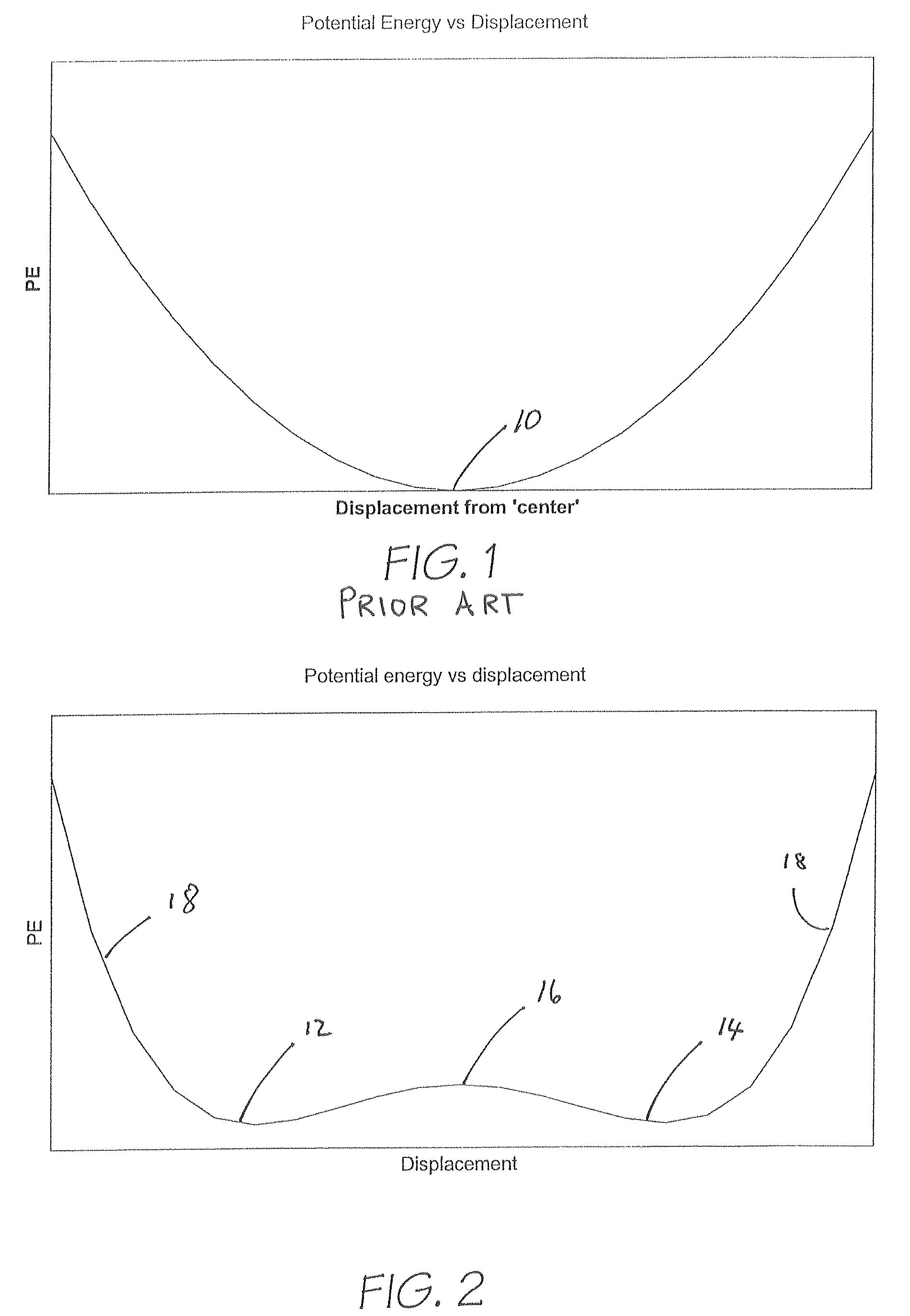
[0033]Referring initially to FIG. 1, it will be noted that the central position of the lens on the eye, indicated at numeral 10 on the graph, is the minimum potential energy position. Movement of the lens away from that position, in either direction, will increase the potential energy of the lens, and accordingly some form of external force will be required to hold the lens in the higher potential energy position.

[0034]FIG. 2, on the other hand, depicts two low potential energy points on the graph, indicated at numerals 12 and 14. These two low energy points will, in accordance with the invention, correspond with the position of the lens on the eye which corresponds with optimal positions of the contact lens for near-viewing and distance-viewing. Optionally, one of those positions is at a lower potential energy than the other position, so that the lowest potential energy position becomes more stable, making it harder to inadvertently leave this position. For safety reasons it is imp...


PUM


Abstract

A contact lens having near vision and distance vision portions, the lens being movable on the eye between first and second positions, those positions corresponding with aligning the wearer's vision through the near vision and distance vision portions respectively. The lens is positionally stable on the eye in each of the two positions, and requires a force to be applied to the lens to move between the first and second positions. Preferably the lens has a back surface and a front surface, and said back surface has either one or two major back curve zones occupying a major portion of the lens back surface.

Description

[0001]This application is a national stage filing under 35 U.S.C. 371 of PCT International Application No. PCT / AU05 / 000101 filed on Jan. 28, 2005, which claims benefits under 35 U.S.C. §119(a)-(d) or §365(b) of Australian Patent Application No. 2004900398 filed Jan. 29, 2004.FIELD OF THE INVENTION[0002]This invention relates to contact lenses, and more particularly to bifocal contact lenses in which at least one primary and one secondary optical zones are present.BACKGROUND OF THE INVENTION[0003]Bifocal lenses are comprised of two or more areas, or zones, with different optical powers, including typically a far-power zone for distance vision, and a near-power zone for near or close up vision. The two zones may be subdivided into additional power zones in which case the lens may be called a multifocal lens.[0004]The retinal image and the visual percept that results from it are dependent upon the light that enters the eye through the entrance pupil. In order for a bifocal contact lens...

Claims


Application Information

Patent Timeline
Patent Type & Authority Patents(United States)
IPC IPC(8): G02C7/04
CPCG02C7/045G02C7/043
Inventor EVANS, SIMON RODNEYHO, ARTHURBRENT, GEOFFREY PETEREHRMANN, KLAUSFALK, DARRIN MARKPERERA, SANDYA INDRANITAN, JACQUELINEDU TOIT, RENEE
Owner THE VISION CRC LTD
Learn More