
Adjustable head for a golf putter

a golf putter and adjustable technology, applied in the field of adjustable putter head, can solve the problems of rarely aiming directly at the center of the putter, and the problem of putting can be problemati

Inactive Publication Date: 2008-02-26
BITONDO GREGORY F
View PDF32 Cites 82 Cited by
  • Summary
  • Abstract
  • Description
  • Claims
  • Application Information

AI Technical Summary

Benefits of technology

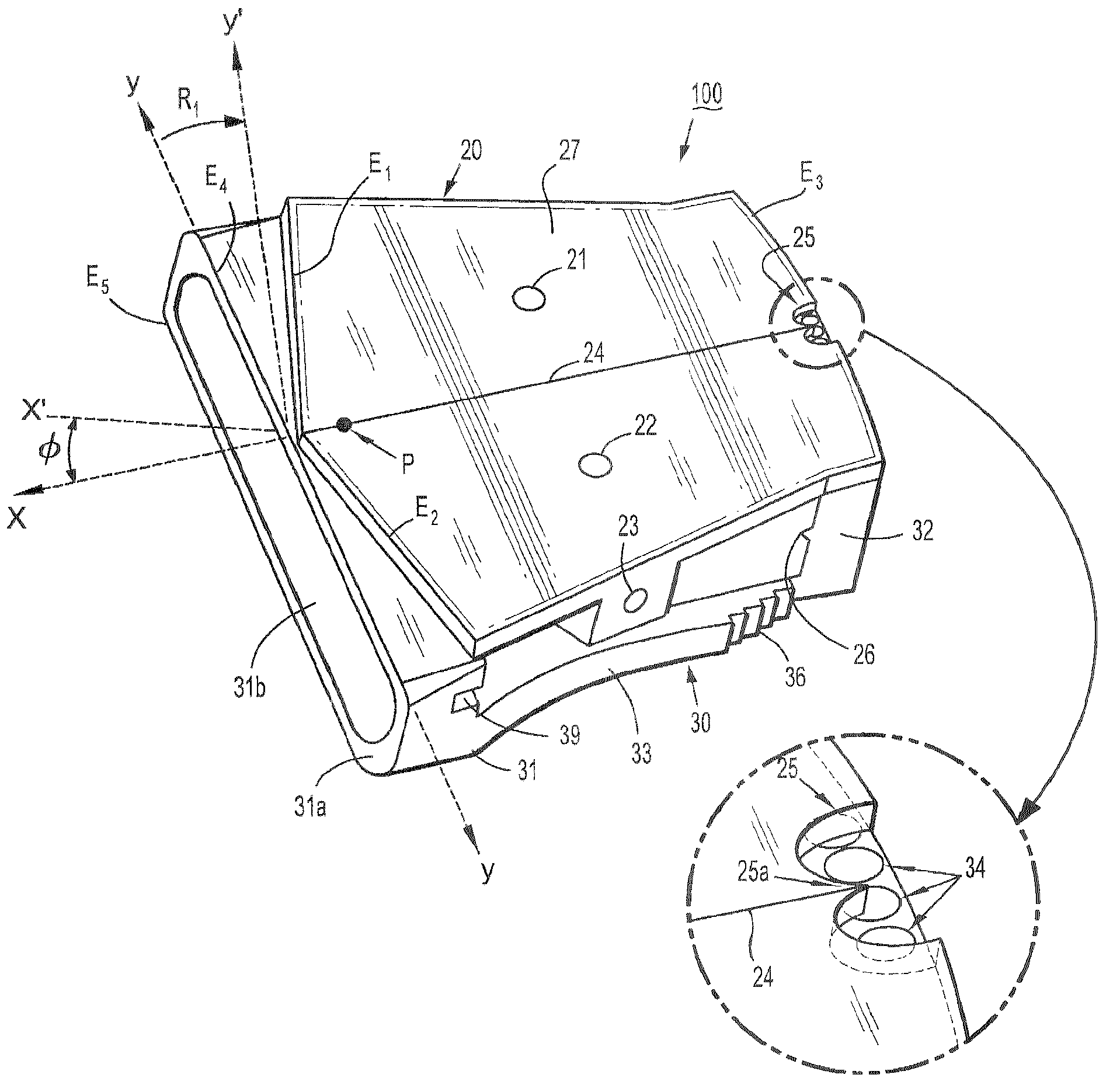
[0010]In general, exemplary embodiments of the invention include golf clubs having adjustable club heads. In particular, an exemplary embodiment of the invention includes an adjustable putter head for a golf putter having an elongated line of sight marking on a top surface of the putter head to aid in aligning the putter head in a putting direction toward a target point, and a putter face which is pivotally connected to the putter head to allow selective adjustment of an angular position of the putter face relative to the line of sight. The selective adjustment serves various purposes such allowing a golfer to adjust a face angle orientation of the putter head to compensate for improper putting strokes or enabling a golfer to line up breaking putts using the line of sight to aim the putt at the hole as a fixed target while adjusting the face angle orientation to align the ball striking face square to a desired off-line direction of intended ball movement.

Problems solved by technology

One of the most challenging aspects of the game of golf involves putting as putting accuracy is based on many factors including, for example, the skill level and ability of the individual, the type of putter used by the individual, etc.
However, a putt is rarely aimed directly dead center at a target hole because there is typically a left or right break (however slight it may be) in the green.
In this regard, putting can be problematic especially when making breaking putts where a golfer must visualize and align to an invisible target line extending towards a blind spot (invisible aiming point) on the green.

Method used


Image

  • Adjustable head for a golf putter
  • Adjustable head for a golf putter
  • Adjustable head for a golf putter

Examples


Embodiment Construction

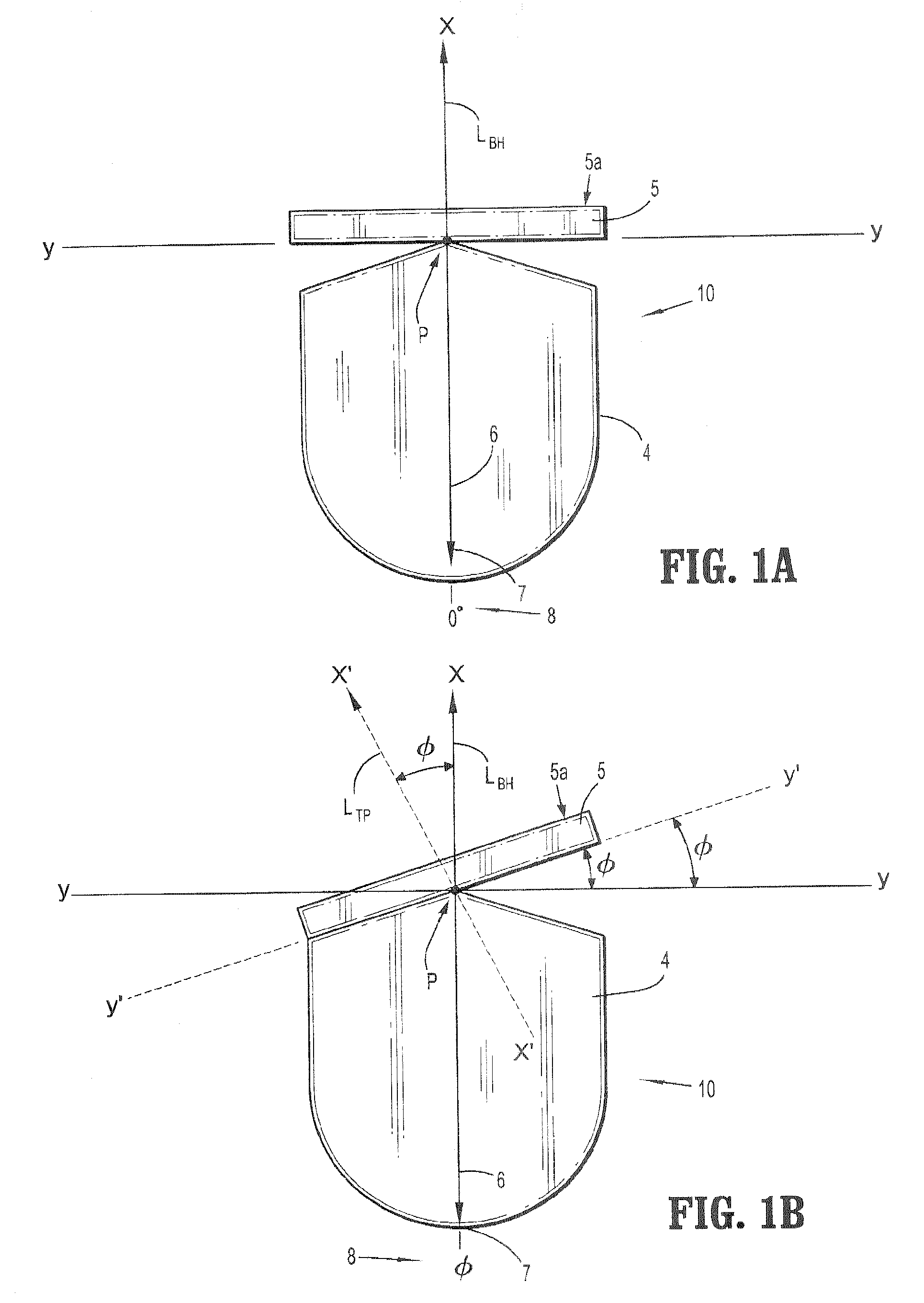
[0025]FIGS. 1A and 1B are high-level top plan schematic illustrations of an adjustable putter head according to an exemplary embodiment of the invention. More specifically, FIGS. 1A and 1B depict a high-level, conceptual framework of an adjustable putter head (10) generally comprising a putter body (4), and a putter face (5) having a planar ball striking face (5a). The body (4) is adapted to be connected to a club shaft (not shown) and comprises an elongated line of sight (6) (or alignment line) which extends along the top surface of the putter body (4) from the front to the rear of the body (4) in a direction of a putting motion. The alignment line (6) is in fixed orientation with the club shaft. The alignment line (6) is a visual aid to assist the golfer in positioning the putter head to be squarely aligned in a direction of a target line (aim line) extending from a golf ball to a target point. Moreover, in the exemplary embodiment, the alignment line (6) is positioned in general ...


PUM


Abstract

An adjustable putter head for a golf putter is designed having an elongated line of sight marking on a top surface of the putter head to aid in aligning the putter head in a putting direction toward a target point, and a putter face which is pivotally connected to the putter head to allow selective adjustment of an angular position of the putter face relative to the line of sight for purposes such as adjusting a face angle orientation to compensate for improper putting strokes, or lining up breaking putts using the line of sight to aim the putt at the hole as a fixed target while adjusting the face angle orientation to align the ball striking face square to an off-line direction of intended ball movement.

Description

TECHNICAL FIELD OF THE INVENTION[0001]The present invention relates generally to golf clubs having adjustable club heads and, in particular, to an adjustable putter head for a golf putter, having an elongated line of sight marking on a top surface of the putter head to aid in aligning the putter head in a putting direction toward a target point, and a putter face which is pivotally connected to the putter head to allow selective adjustment of an angular position of the putter face relative to the line of sight for purposes such as adjusting a face angle orientation to compensate for improper putting strokes or lining up breaking putts using the line of sight to aim the putt at the hole as a fixed target while adjusting the face angle orientation to align the ball striking face square to an off-line direction of intended ball movement.BACKGROUND[0002]One of the most challenging aspects of the game of golf involves putting as putting accuracy is based on many factors including, for ex...

Claims


Application Information

Patent Timeline
IPC IPC(8): A63B69/36A63B53/06
CPCA63B53/0487A63B53/065A63B49/06A63B2053/0416A63B2053/0437A63B2053/0433A63B2053/0441A63B53/0416A63B53/0433A63B53/0437A63B53/0441A63B60/52
Inventor BITONDO, GREGORY F.
Owner BITONDO GREGORY F
Learn More