
Calcaneal bisector

a calcaneal and bisector technology, applied in the field of calcaneal bisectors, can solve the problems of low reliability of this conventional method, and achieve the effect of indicating the calcaneal bisection line more accurately and conveniently

Active Publication Date: 2008-02-19
THE HONG KONG POLYTECHNIC UNIV
View PDF8 Cites 3 Cited by
  • Summary
  • Abstract
  • Description
  • Claims
  • Application Information

AI Technical Summary

Benefits of technology

The present invention is a device for aligning the heel of a person's foot during a medical procedure. The device includes a frame and two plates that can be moved relative to each other to align with the heel. An indicator is also included to indicate the alignment of the plates and the position of the heel. The device uses a transmission mechanism to correlate the movements of the indicator and the plates to accurately determine the position of the heel. This device helps to ensure accurate alignment of the heel during medical procedures, which can improve the quality and effectiveness of the procedure.

Problems solved by technology

Obviously low reliability may exist with this conventional method.

Method used


Image

  • Calcaneal bisector
  • Calcaneal bisector
  • Calcaneal bisector

Examples


Embodiment Construction

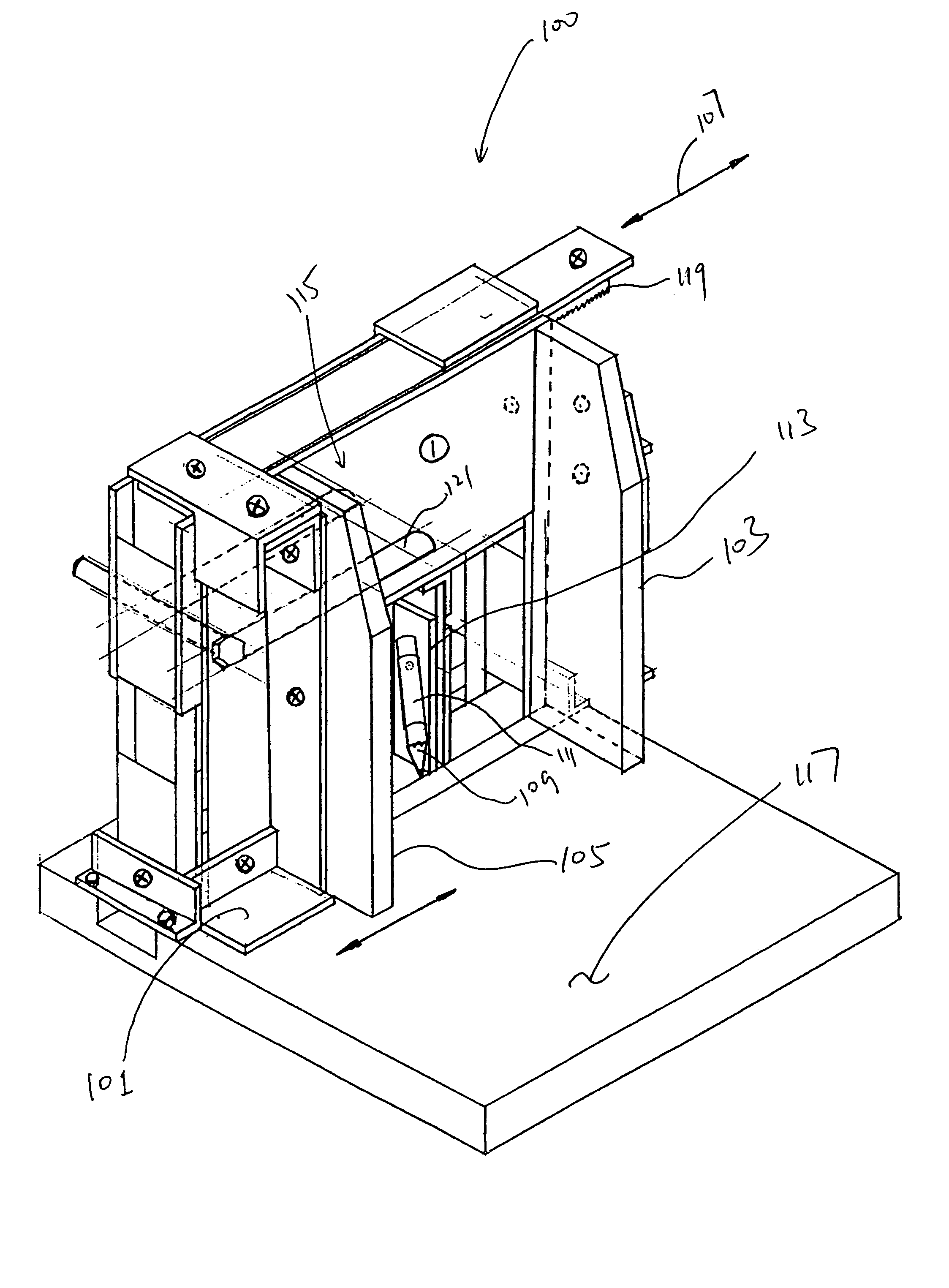
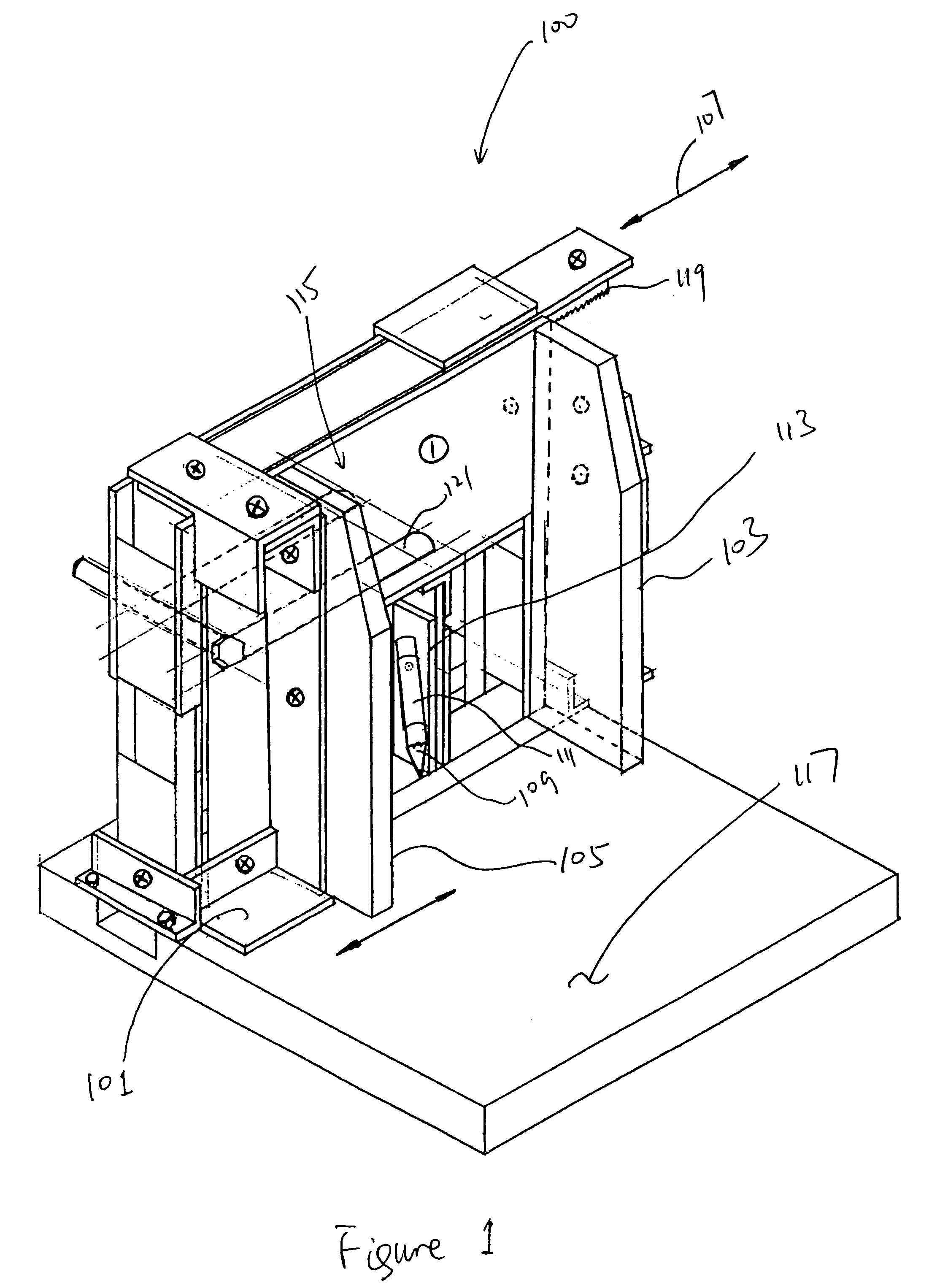
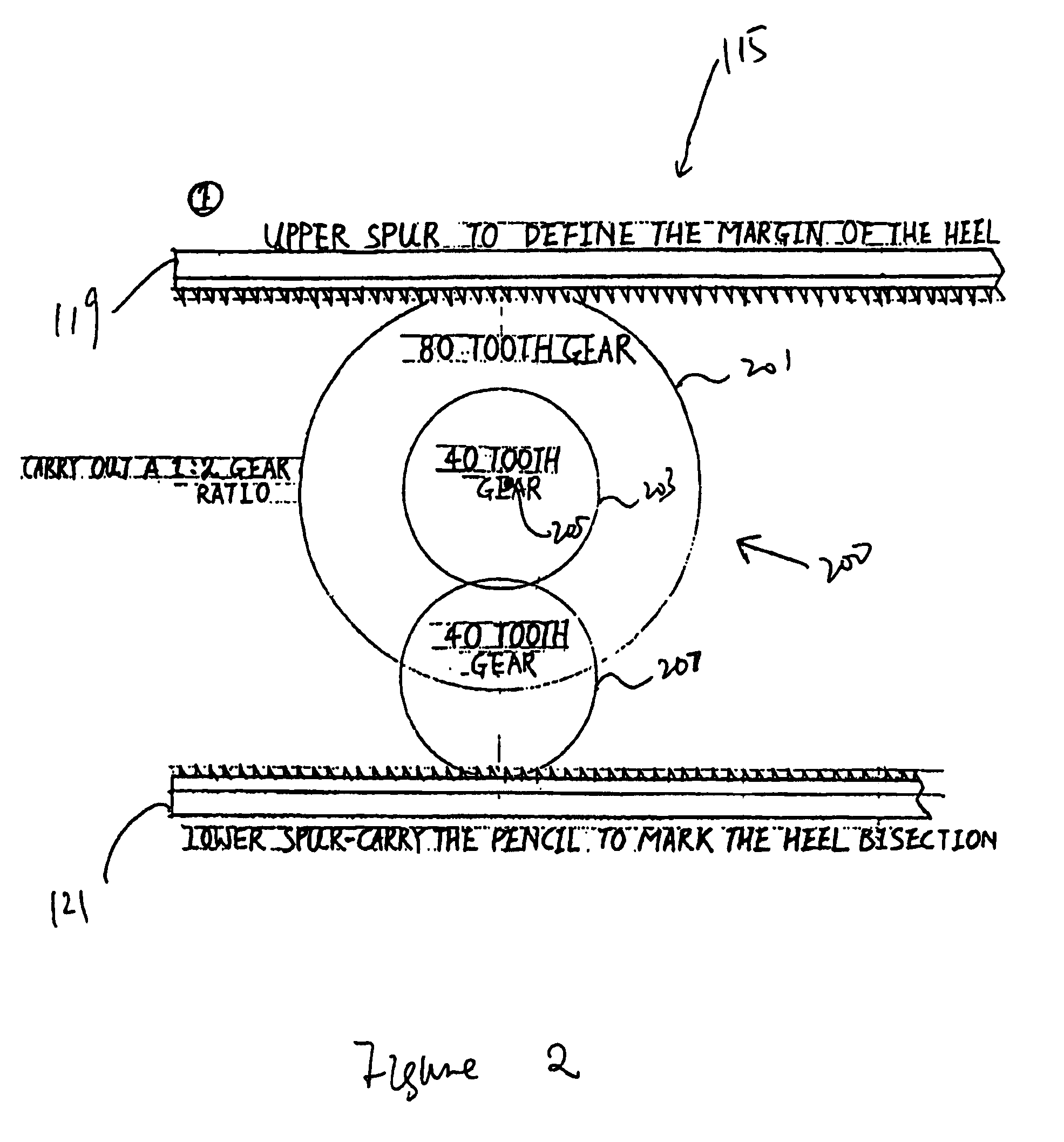
[0012]As shown in FIG. 1, a calcaneal bisector embodiment 100 of the present invention firstly includes a frame generally indicated as 101 and a pair of reference plates 103, 105 parallel to each other. One of the reference plates 103 is fixedly mounted to the frame 101. The other reference plate 105 is movably mounted to the frame 101 and may slide relative to the fixed plate 103 in a directional 107 perpendicular to the fixed reference plate 103 for clipping the heel 301 (see FIG. 3B) along its width when the bisector 100 is in use. A pen 109, which functions as an indicator to draw the bisection line on the heel in the exemplary embodiment, is slidably inserted in a longitudinal pen holder 111, which is rotatably mounted to a piece of movable pen-holder-plate 113. In the exemplary embodiment, the movements of the pen-holder-plate 113 are synchronized with the movements of the movable reference plate 105 through a transmission mechanism, which is generally indicated as 115. When t...


PUM


Abstract

A calcaneal bisector for indicating a calcaneal bisection line of a heel firstly includes a frame and a first plate mounted relative to the frame. One side of the heel can be aligned to the first plate when the bisector is in use. The bisector also includes a second plate movably mounted to the frame, and the second plate is slidable relative to the first plate for aligning to the other side of the heel. The bisector further includes an indicator movably mounted relative to the frame for indicating the calcaneal bisection line and a transmission mechanism disposed between the plates and the indicator for correlating movements of the indicator and the relative movements of the plates so as to ascertain the calcaneal bisection line.

Description

BACKGROUND[0001]1. Field of the Invention[0002]The present invention relates to technologies for indicating a calcaneal bisection line of a heel.[0003]2. Background of the Invention[0004]In clinical practice of foot orthotics, a calcaneal bisection line of the posterior heel surface is commonly used as the reference for orthotic designs. Conventionally, a caliper and a ruler are used to mark two mid points at two separate levels on the heel, and a bisection line can be drawn by joining these two points together. Obviously low reliability may exist with this conventional method.OBJECT OF THE INVENTION[0005]Therefore, it is an object of the present invention to provide an apparatus for indicating the calcaneal bisection line of the heel more accurately and conveniently, or at least provide the public with a useful choice.SUMMARY OF THE INVENTION[0006]According to an aspect of the present invention, a calcaneal bisector for indicating a calcaneal bisection line of a heel firstly includ...

Claims


Application Information

Patent Timeline
Patent Type & Authority Patents(United States)
IPC IPC(8): A43D1/00
CPCA43D1/02
Inventor LAU, CHUN-PONGLEUNG, KAM-LUN
Owner THE HONG KONG POLYTECHNIC UNIV
Learn More