Tape drive apparatus, tape extraction apparatus and tape cassette

a drive apparatus and tape cartridge technology, applied in the direction of record information storage, instruments, printers, etc., can solve the problems of tape cartridge removal, time and effort, unstable relationship between the hook and the hole, etc., and achieve the effect of reliable on the takeup reel

Inactive Publication Date: 2007-08-07
SONY CORP
View PDF31 Cites 0 Cited by
  • Summary
  • Abstract
  • Description
  • Claims
  • Application Information

AI Technical Summary

Benefits of technology

[0011]The chucking mechanism in the carrying mechanism, which carries the leader block of the magnetic tape, may allow a stable and reliable move of the leader block between the cartridge mounting side and the takeup reel.
[0035]When the leader block is inserted into the takeup reel, the engaging protrusion section of the takeup reel is engaged with the engaging depression section of the leader block, thereby holding the leader block stably and reliably on the takeup reel.

Problems solved by technology

However, the leader tape, being a flexible resin film, cannot move smoothly and stably to fetch the magnetic tape, and the leader tape also shakes as its hook end vertically faces the hook hole of the end of the magnetic tape, rendering the mutually facing relationship between the hook and hole unstable, and frequently resulting in errors in engaging.
On an error in engaging, no second attempt is available, and the tape cartridge must be removed once and remounted at the expense of time and effort.

Method used


Image

  • Tape drive apparatus, tape extraction apparatus and tape cassette
  • Tape drive apparatus, tape extraction apparatus and tape cassette
  • Tape drive apparatus, tape extraction apparatus and tape cassette

Examples


Embodiment Construction

[0063]Hereinafter, an embodiment of the present invention will be described with reference to the drawings.

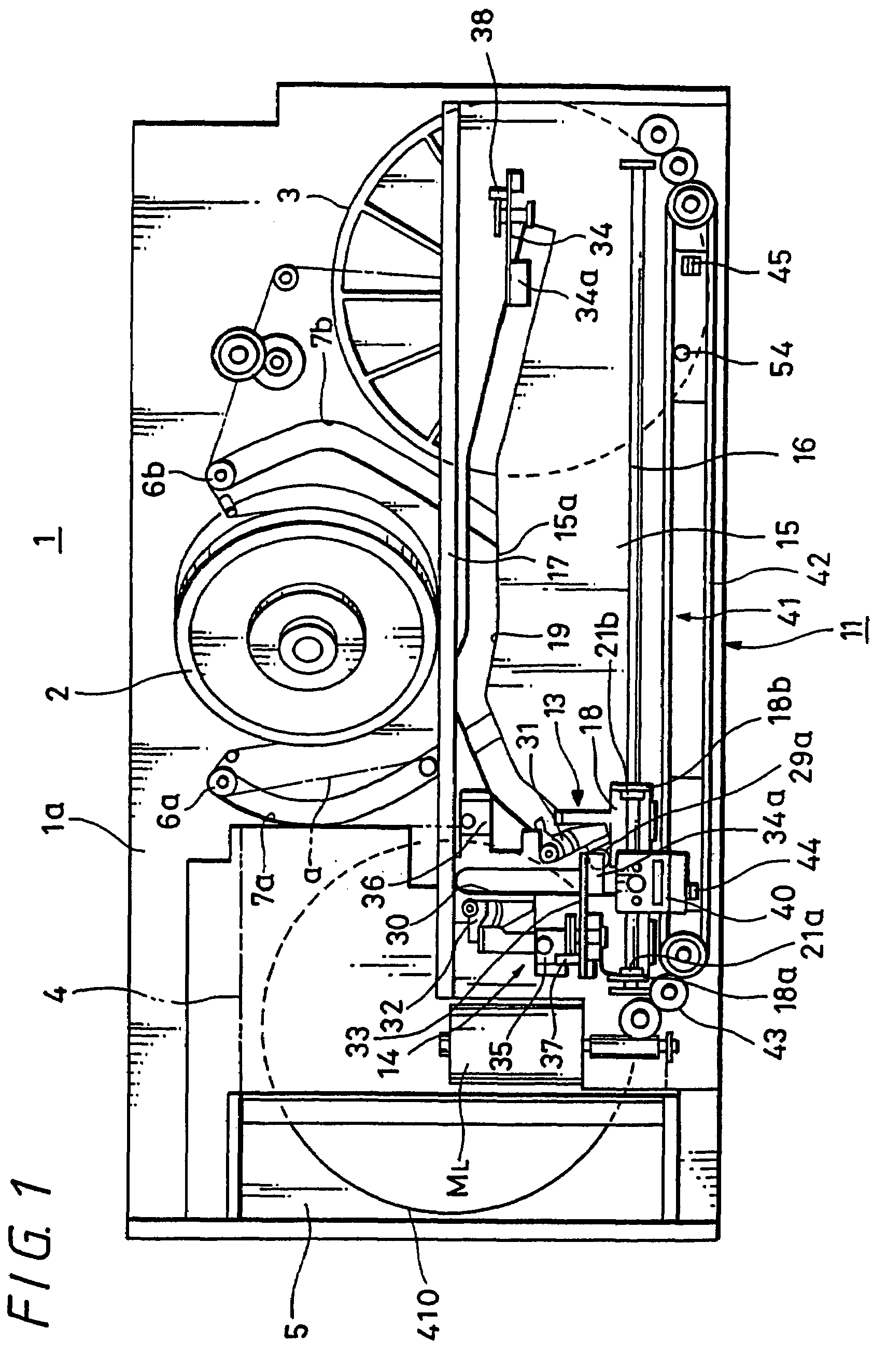
[0064]FIG. 1 shows an embodiment of the present invention, describing a general constitution of a helical scan tape drive apparatus. The figure shows the tape drive apparatus in its horizontal position, however, the tape drive apparatus may be placed to operate in vertical or any other positions.

[0065]In FIG. 1, numeral 1 denotes an entire tape drive apparatus. The tape drive apparatus 1 comprises a rotating magnetic head apparatus on a base chassis 1a for recording / reproducing information by sliding over and in contact with a magnetic tape, and a drum 2 of the rotating magnetic head apparatus is disposed between a takeup reel 3 and a cartridge mount mechanism 5 for a tape cartridge 4 housing a magnetic tape T. Guide paths 7a and 7b for respective loading pins 6a and 6b which constitute a tape loading mechanism are formed on both sides of the drum 2, forming a tape path a from ...


PUM

PropertyMeasurementUnit
magneticaaaaaaaaaa
flexibleaaaaaaaaaa
timeaaaaaaaaaa

Abstract

The invention proposes a tape drive apparatus, tape extraction apparatus and tape cartridge that enable a reliable chucking and chucking release, and a stable carrying of a tape being extracted from a cartridge. The invention is constituted by a magnetically recording / reproducing apparatus; a cartridge mount mechanism 5 whereon a tape cartridge 4 with the magnetic tape T wound therein is mounted; a takeup reel 3 to wind up magnetic T thereon; a leader block 12 attached to one end of the magnetic tape T with a rotation restriction section provided thereon; a chucking mechanism 14 which comprises a chucking pin 27 that restricts the rotation of the leader block and chucks the leader block 12, chucking and releasing chucking of the leader block 12; a carrying mechanism 11 which comprises the carrying section 13 for carrying the chucked leader block 12; a chucking release levers 33 and 34 which releases chucking of the chucking mechanism 14, which is actuated by cams 35 and 36 provided on the carrying section 13 and disposed on both ends of the cam groove 19 for guiding the movement of the leader block 12; and reel motors 53C and 53T including frequency generators 52C and 52T for rotationally driving the tape reel 410 within the tape cartridge 4 and the takeup reel 3, respectively.

Description

CROSS REFERENCE TO RELATED APPLICATIONS[0001]This is a divisional of co-pending U.S. application No. 10 / 181,308, filed on Apr. 11, 2003, which is incorporated herein by reference to the extent permitted by law.TECHNICAL FIELD[0002]The present invention relates to a tape drive apparatus, tape extraction apparatus and tape cartridge, in which a magnetic tape being used as a recording medium is extracted from a tape cartridge and carried to be wound onto a takeup reel provided within a drive unit such that information is recorded and / or reproduced on the magnetic tape.BACKGROUND OF THE INVENTION[0003]The tape drive apparatus that uses a single reel tape cartridge has been in existence. While the existing single reel tape cartridge may be small and convenient for the user to handle or carry it, the cartridge requires, when mounted on the tape drive apparatus, that the tape be extracted from its cartridge and wound onto a takeup reel which is provided within the drive unit.[0004]To meet ...

Claims


Application Information

Patent Timeline
Patent Type & Authority Patents(United States)
IPC IPC(8): G11B15/67G11B23/107G11B15/675
CPCG11B15/67G11B15/6751G11B23/107
Inventor KUROKAWA, TOSHIYADAIBA, JOICHIMAEKAWA, KATSUMIKANO, YASUAKIMITANI, ATSUSHI
Owner SONY CORP
Why Eureka
Try Eureka