
Collision air bag and flotation system

a technology of collision air bag and flotation system, which is applied in the direction of electric devices, pedestrian/occupant safety arrangements, tractors, etc., can solve the problems of air bags, vehicle passengers' injuries, air pollution in vehicles, etc., and achieve the effect of reducing the impact of the vehicle and reducing the velocity of the vehicl

Inactive Publication Date: 2007-06-19
HAKKI SAM +1
View PDF202 Cites 86 Cited by
  • Summary
  • Abstract
  • Description
  • Claims
  • Application Information

AI Technical Summary

Problems solved by technology

In serious impacts, as the front end of a vehicle crushes, the occupants continue to move forward, even with lap and shoulder belts.
However, minute particles and molten materials from combustion products resulting from the combustion of ignitable gas generating material may be discharged from the air bag into the inside of the vehicle causing contamination of the air within the vehicle.
Since an inflating air bag introduces additional energy into a collision, air bags have, in some instances caused injury to passengers of vehicles.
Open weave construction may inflict burns due the hot inflating gas which passes through an opened weave structure.
It is known that very coarse, stiff and dense weave construction could injure the occupants.
Therefore, as the bag compresses, the vehicle decelerates, taking longer to compress each subsequent length of the air bag.
When reduced to practice, an un-vented air bag slows a vehicle at a fast and exponential rate.
A rapid rate of deceleration produces severe effects on the occupants of a rapidly decelerating vehicle.
These effects include the compression of vital organs, such as the brain and heart, which may result in severe injury and death.
Rates of deceleration exceeding 18 g's are not tolerated by humans.
A major drawback of the design is that it may take 200 milliseconds to fully inflate the airbags for an average vehicle.

Method used


Image

  • Collision air bag and flotation system
  • Collision air bag and flotation system
  • Collision air bag and flotation system

Examples


first embodiment

[0115]FIG. 7 is a magnified sectional view illustrating pressure relief member 70 for the plurality of nested inflatable air bags 40. In this example, a first pressure relief member 71 is shown located on the first inflatable air bag 41. The pressure relief member 71 is shown as a frangible seam 80A. The frangible seam 80A comprises a first sheet material 81A secured to a second sheet material 82A secured by a connector 83A. The connector 83A may comprise an adhesive, a stitch, a frangible patch or any other suitable means for creating a pressure relief member 71. The first sheet material 81A is secured to the second sheet material 82A to fracture when a predetermined pressure is applied to the first inflatable air bag 41.

[0116]FIG. 8 is a view similar to FIG. 7 illustrating the rupturing of the frangible seam 80A. When a predetermined pressure is applied to the first inflatable air bag 41, the frangible seam 80A ruptures for enabling a controlled deflation of the first inflatable a...

second embodiment

[0117]FIG. 9 is a magnified sectional view illustrating pressure relief member 71 for the first inflatable air bag 41 shown as a pressure relief valve 80B. The pressure relief valve 80B comprises a valve member 81B for closing a deflation aperture 82B. A spring 83B urges the valve member 81B in a closed position for closing the deflation aperture 82B.

[0118]FIG. 10 is a view similar to FIG. 8 illustrating the opening of the pressure relief valve 80B. When a predetermined pressure is applied to the first inflatable air bag 41, the internal pressure within the first inflatable air bag 41 opens the valve member 81B against the urging of spring 83B to open the deflation aperture 82B.

[0119]A plurality of pressure relief members 70 are connected to the plurality of nested inflatable air bags 40 for sequentially deflating the plurality of nested inflatable air bags 40 upon sequential impact of the plurality of nested inflatable air bags 40 with the object 68. Each of the pressure relief mem...


PUM


Abstract

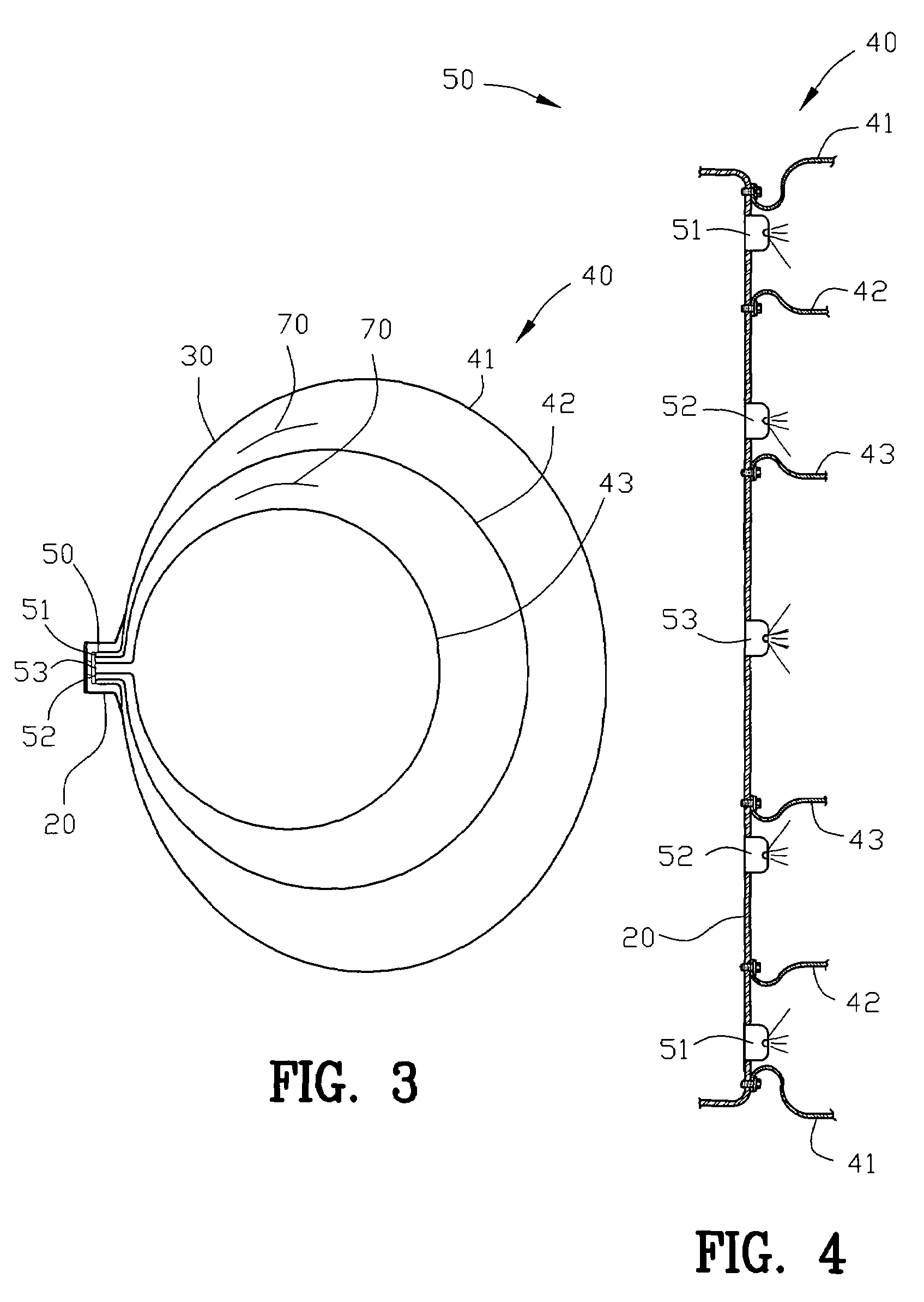
A pre-impact inflation air bag system for a vehicle having a preselected decreasing distance between the vehicle and an object is disclosed. The system comprises a plurality of nested inflatable air bags. A plurality of inflators are provided for inflating the plurality of nested inflatable air bags, respectively. A collision sensor produces a collision sensor output upon detecting the object with the preselected decreasing distance between the vehicle and the object. A controller receives the collision sensor output for simultaneously inflating each of the plurality of nested inflatable air bags between vehicle and an object. A plurality of pressure relief members are connected to the plurality of nested inflatable air bags for sequentially deflating the plurality of nested inflatable air bags upon sequential impact of the plurality of nested inflatable air bags with the object.

Description

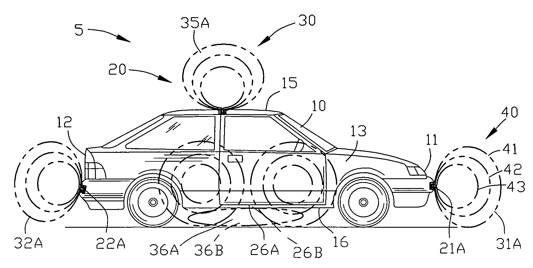
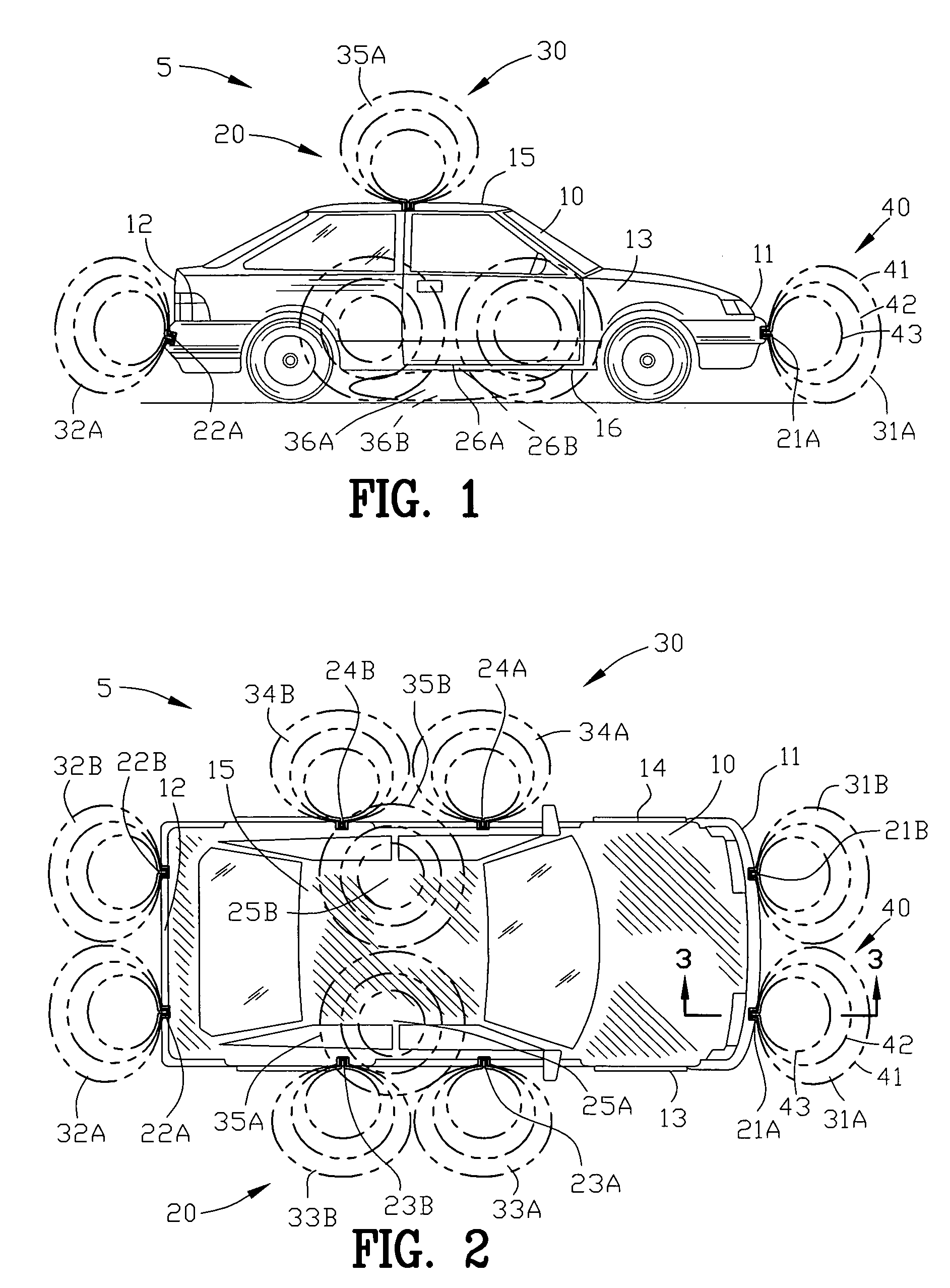
CROSS-REFERENCE TO RELATED APPLICATIONS[0001]This application claims benefit of U.S. provisional application Ser. No. 60 / 603,982 filed Aug. 24, 2004. All subject matter set forth in provisional application Ser. No. 60 / 603,982 is hereby incorporated by reference into the present application as if fully set forth herein.BACKGROUND OF THE INVENTION[0002]1. Field of the Invention[0003]This invention relates to a vehicle safety systems, and more particularly to an improved collision air bag and flotation system for a land vehicle, air or marine vehicle or craft.[0004]2. Background of the Invention[0005]Air bags work in conjunction with lap and shoulder belts to protect the passengers of a vehicle involved in rapid deceleration, as in an impact with a fixed object or another vehicle. Frontal impact air bags are designed to prevent serious injury by keeping the occupant head and chest of the occupant from impacting the steering wheel, dashboard or windshield. In serious impacts, as the fro...

Claims


Application Information

Patent Timeline
Patent Type & Authority Patents(United States)
IPC IPC(8): B60K28/00
CPCB60R19/205B60R21/0134B60R21/36B60R21/239B60R2021/0016B60R2021/0088B60R2021/0093B60R2021/138B60R2021/23332
Inventor HAKKI, SAMHAKKI, A-HAMID
Owner HAKKI SAM
Learn More