
Wafer holding apparatus

a technology of holding apparatus and wafer, which is applied in the direction of lighting and heating apparatus, furniture, charge manipulation, etc., can solve the problems of deterioration in reliability, increase in weight, and cost hike, and achieve the effect of preventing the occurrence of wafer leaping and holding the wafer stabl

Inactive Publication Date: 2007-03-06
YASKAWA DENKI KK
View PDF15 Cites 21 Cited by
  • Summary
  • Abstract
  • Description
  • Claims
  • Application Information

AI Technical Summary

Benefits of technology

[0008]The invention is also aimed at providing a wafer holding apparatus which enables stable holding action by preventing occurrence of leaping of a wafer.

Problems solved by technology

Therefore, the accompanying complicated configuration of the wafer holding apparatus leads to a problem, such as a cost hike, an increase in weight, or deterioration in reliability.
Hence, there arises another problem in that, when the pressing element presses the wafer W, the wafer W sometimes leaps up while the stopper pins 6 serve as fulcrums, thereby causing difficulty in realization of stable holding.
The top faces of the support pins 7 are flat, leading to still another problem of a large contact area existing between the support pins 7 and the wafer W, thereby leading to adhesion of large amounts of particles.

Method used


Image

  • Wafer holding apparatus
  • Wafer holding apparatus
  • Wafer holding apparatus

Examples


Embodiment Construction

[0016]An embodiment of the invention will be described hereinbelow by reference to the drawings. Elements which are common to those of the related-art wafer holding apparatus are assigned the same reference numerals, and their repeated explanations are omitted.

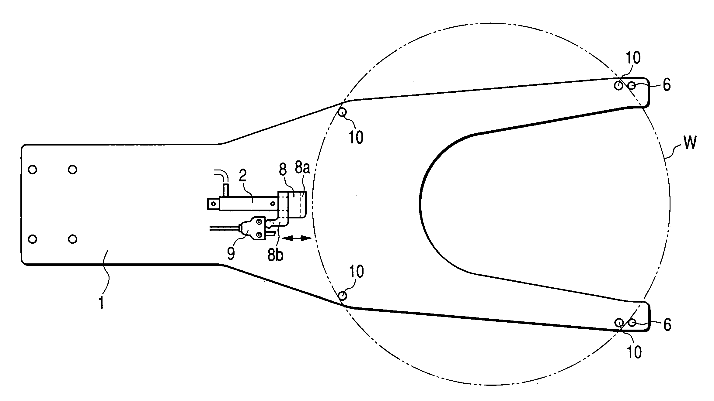
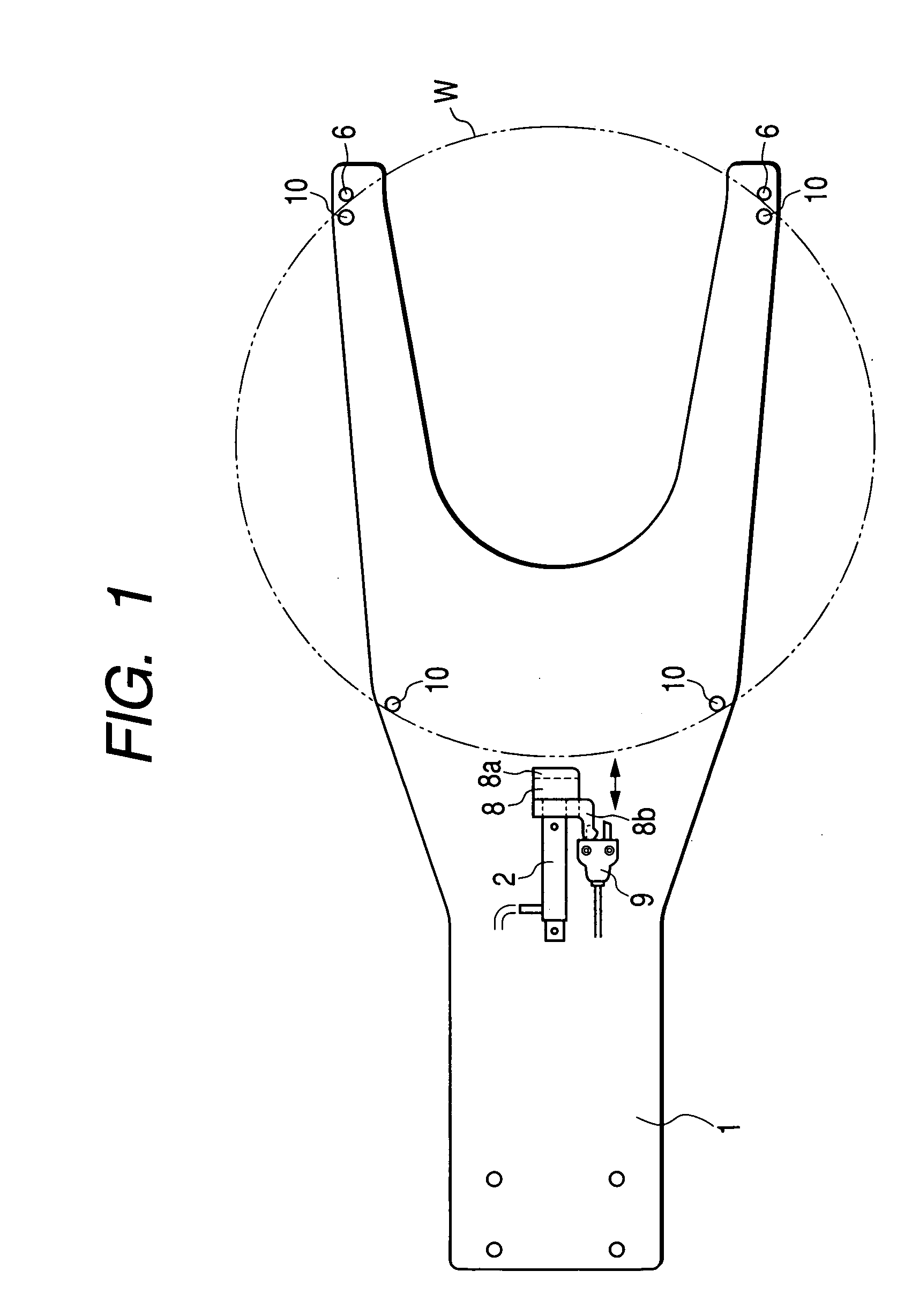
[0017]FIG. 1 is a plan view of a wafer holding apparatus, showing an embodiment of the invention. In the drawing, reference numeral 8 designates a pressing element which is attached to an air cylinder 2 and advances or recedes in a longitudinal direction. Reference numeral 9 designates an operation confirmation sensor to be used as detection means, the means detecting the position of the pressing element 8 and ascertaining gripping and presence / absence of a wafer W. Reference numeral 10 designates support pins provided for supporting the wafer W.

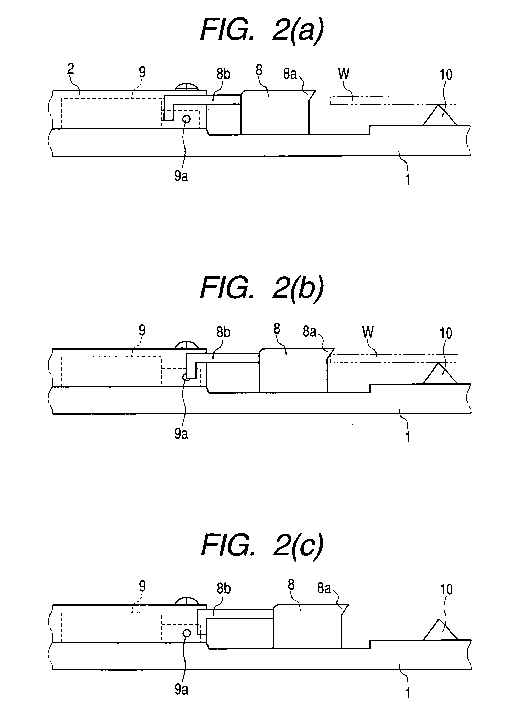
[0018]FIGS. 2(a) to 2(c) show the descriptive view showing functions of the wafer holding apparatus, showing the embodiment of the invention. FIG. 2(a) shows a state of the wafer holdi...


PUM

PropertyMeasurementUnit
Areaaaaaaaaaaa

Abstract

The invention provides a wafer holding apparatus which enables ascertainment of gripping and presence / absence of a wafer through use of single detection means.The apparatus has drive means (2) having a pressing element (8) which advances or recedes in a longitudinal direction; and detection means (9) for detecting advancement / receding of the pressing element (8). When the detection means (9) has detected that the pressing element (8) has advanced to and come to a halt at a predetermined position, the wafer is determined to be properly held. When the detection means (9) has detected that the pressing element (8) has advanced in excess of the predetermined position, the wafer is determined not to be present on the wafer holding apparatus.

Description

FIELD OF THE INVENTION [0001]The invention relates to a wafer holding apparatus to be attached to the extremity of a robot arm which transfers a wafer within a semiconductor manufacturing apparatus or between pieces of semiconductor manufacturing apparatus, and more particularly, to a wafer holding apparatus which supports a wafer by gripping an outer edge of a wafer.BACKGROUND ART [0002]An apparatus which supports a wafer by gripping an outer edge of the wafer has hitherto been known as an apparatus which is to be attached to an extremity of an arm of a wafer transport robot and grips a wafer.[0003]FIG. 3 shows a related-art example of such a wafer holding apparatus. In the drawing, reference numeral 1 designates a base material of the wafer holding apparatus. The base material 1 is a thin plate with a bifurcated extremity. Reference 2 designates an air cylinder which is secured on a root of the base material 1 and serves as drive means for actuating a pressing piece 3 attached to ...

Claims


Application Information

Patent Timeline
IPC IPC(8): H01L21/302B25J15/08B65G49/07H01L21/00H01L21/677H01L21/68H01L21/687
CPCH01L21/67259H01L21/68707H01L21/6835H01L21/68
Inventor ASANO, HIROSHI
Owner YASKAWA DENKI KK
Learn More