
Cell phone tower antenna tilt and heading control

Inactive Publication Date: 2007-02-06
WENSINK JAN B +1
View PDF3 Cites 52 Cited by
  • Summary
  • Abstract
  • Description
  • Claims
  • Application Information

AI Technical Summary

Benefits of technology

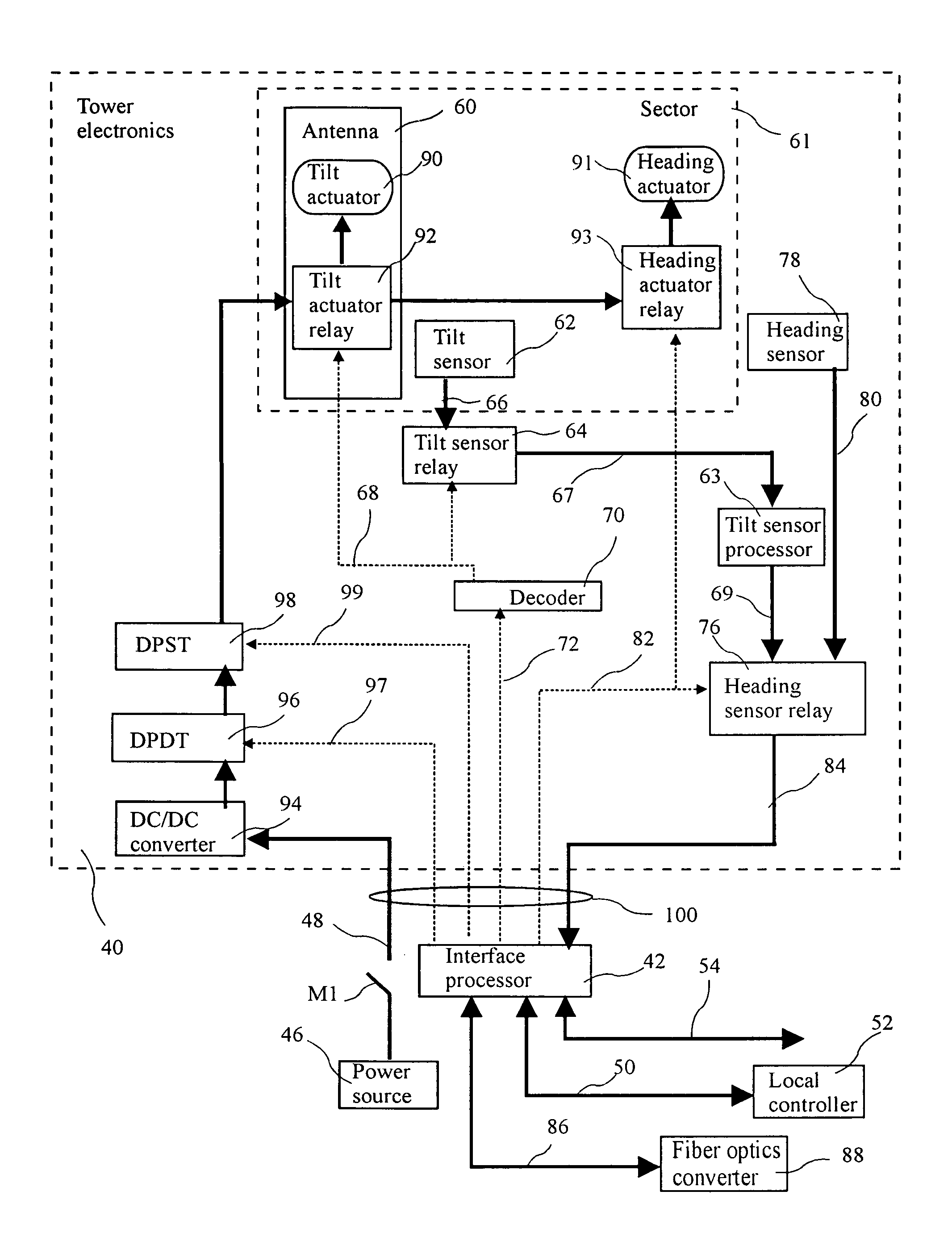
[0007]The present invention addresses the above and other needs by providing a cell phone antenna system having simple mechanical tilt and heading adjustments. The antennas are mounted to towers or other structures, and include sensors for measuring antenna tilt and/or heading. A single sensor signal is selected and provided to an interface unit

Problems solved by technology

However, over time both the physical orientation of the tower may shift, or the requirements for cell coverage may change due to new cells coming online, or due to usage changes.
Further, changes in weather or construction of new structures may affect cell coverage.
Such manual adjustment was time consuming, costly, possibly dangerous, and required system downtime.
Although the problems associated with manual tilt adjustment are addressed by the antenna system described in the '744 patent, the use of electronic tilt adjustment alters the shape of the beams.
Because the antennas are designed to optimize beam shape for a non-steered beam, it may be assumed that electronic beam steering results in a less than optimal beam shape.
Further, the requirement for individual controllers for each antenna results in substantial cost and complexity, and the '744 patent does not address beam heading (i.e., azimuth).

Method used


Image

  • Cell phone tower antenna tilt and heading control
  • Cell phone tower antenna tilt and heading control
  • Cell phone tower antenna tilt and heading control

Examples


Embodiment Construction

[0027]The following description is of the best mode presently contemplated for carrying out the invention. This description is not to be taken in a limiting sense, but is made merely for the purpose of describing one or more preferred embodiments of the invention. The scope of the invention should be determined with reference to the claims.

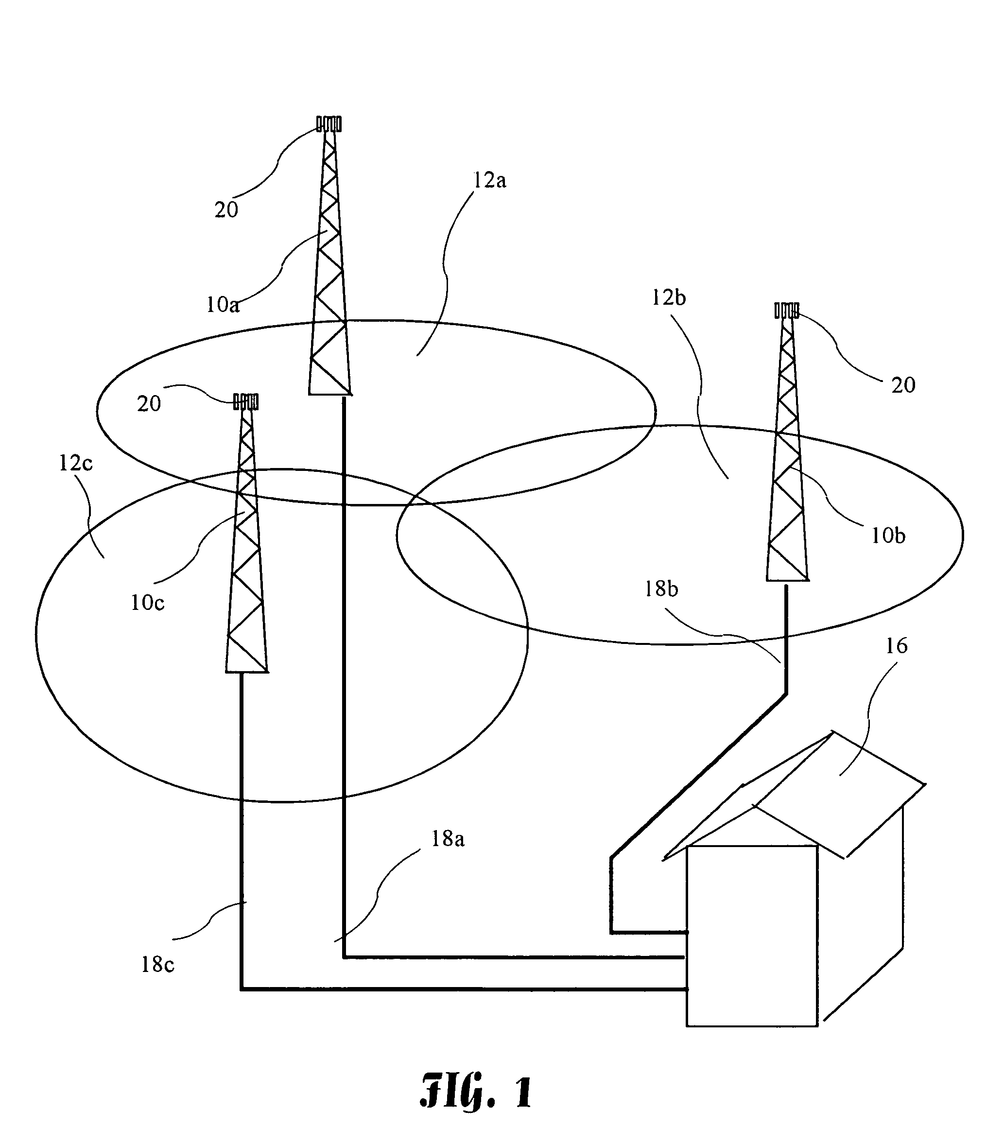
[0028]A cell phone system having cooperating cells 12a–12c and a switching center 16 is shown in FIG. 1. Each cell 12a–12c includes a tower 10a–10c, and each tower includes an antenna array 20. The towers 10a–10c are connected by communications lines 18a–18c to the switching center 16. The switching center 16 monitors the activity in cells 12a–12c, and switches individual cell phones between the cells 12a–12c as needed to maintain contact between the cell phones and the cells 12a–12c, and to balance loads between cells 12a–12c.

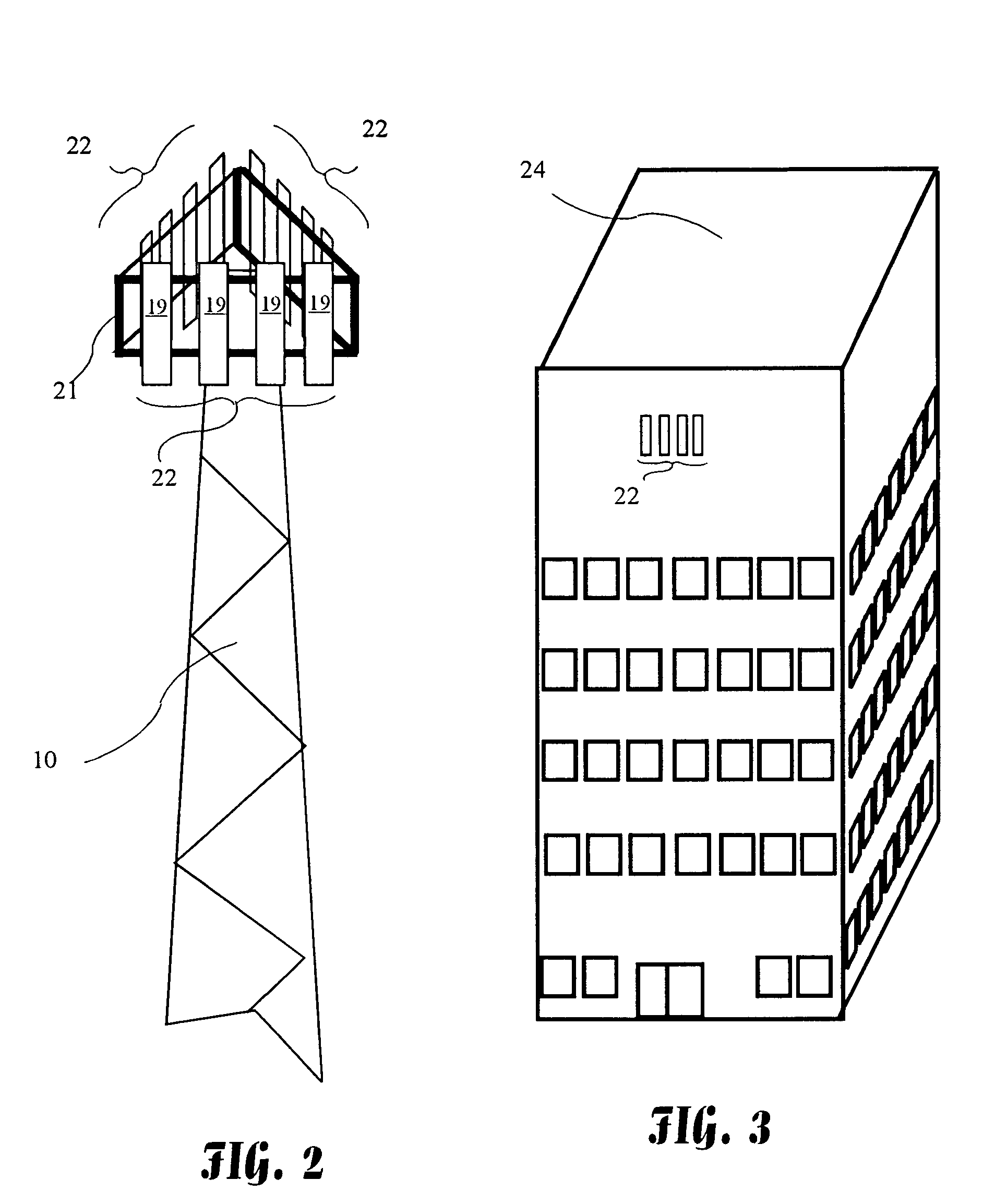
[0029]Three antenna sectors 22 arranged in a triangle are shown mounted to a tower 10 using antenna mounts 21 in FIG. 2. ...


PUM


Abstract

A cell phone antenna system having simple mechanical tilt and heading adjustments. The antennas are mounted to towers or other structures, and include sensors for measuring antenna tilt and / or heading. A single sensor signal is selected and provided to an interface unit. The interface unit processes the sensor signal and provides sensor information to one or more local or remote processors used to control or monitor the antennas. Antenna control signals generated by the local or remote processors may be provided to the interface unit, and resulting power signals directed to individual actuators on the antennas.

Description

BACKGROUND OF THE INVENTION[0001]The present invention relates to control of antenna tilt and heading, and more particularly to an efficient system for adjusting antenna tilt and heading from the base of the antenna tower or from a remote site.[0002]Cell phone systems are rapidly becoming a common mode of communications. The cost of using such systems has dropped rapidly over the past few years, and due to the convenience, many individuals rely solely on cell phones. The resulting substantial increase in use and the competition between service providers has provided significant motivation to maximize the efficiency of cell phone systems.[0003]Cell phone systems involve the cooperation of cell phones operated by individual subscribers within the cells. The cells communicate with the cell phones and relay signals to central facilities which form connections with the desired destination which could be another cell phone or a conventional phone. An important characteristic of cell phone...

Claims


Application Information

Patent Timeline
IPC IPC(8): H01Q3/02
CPCH01Q1/246H01Q1/125
Inventor WENSINK, JAN B.THINN, JOSEPH D.
Owner WENSINK JAN B
Learn More