
Spark ignition modifier module and method

a technology of spark ignition and modifier, which is applied in the direction of spark plugs, combustion engines, electrical equipment, etc., can solve the problems of excessive pollutants and require relatively high octane ratings of fuel, and achieve the effect of enhancing the efficiency of operation of a common prior art combustion engin

Inactive Publication Date: 2006-09-12
SMARTPLUG
View PDF11 Cites 66 Cited by
  • Summary
  • Abstract
  • Description
  • Claims
  • Application Information

AI Technical Summary

Benefits of technology

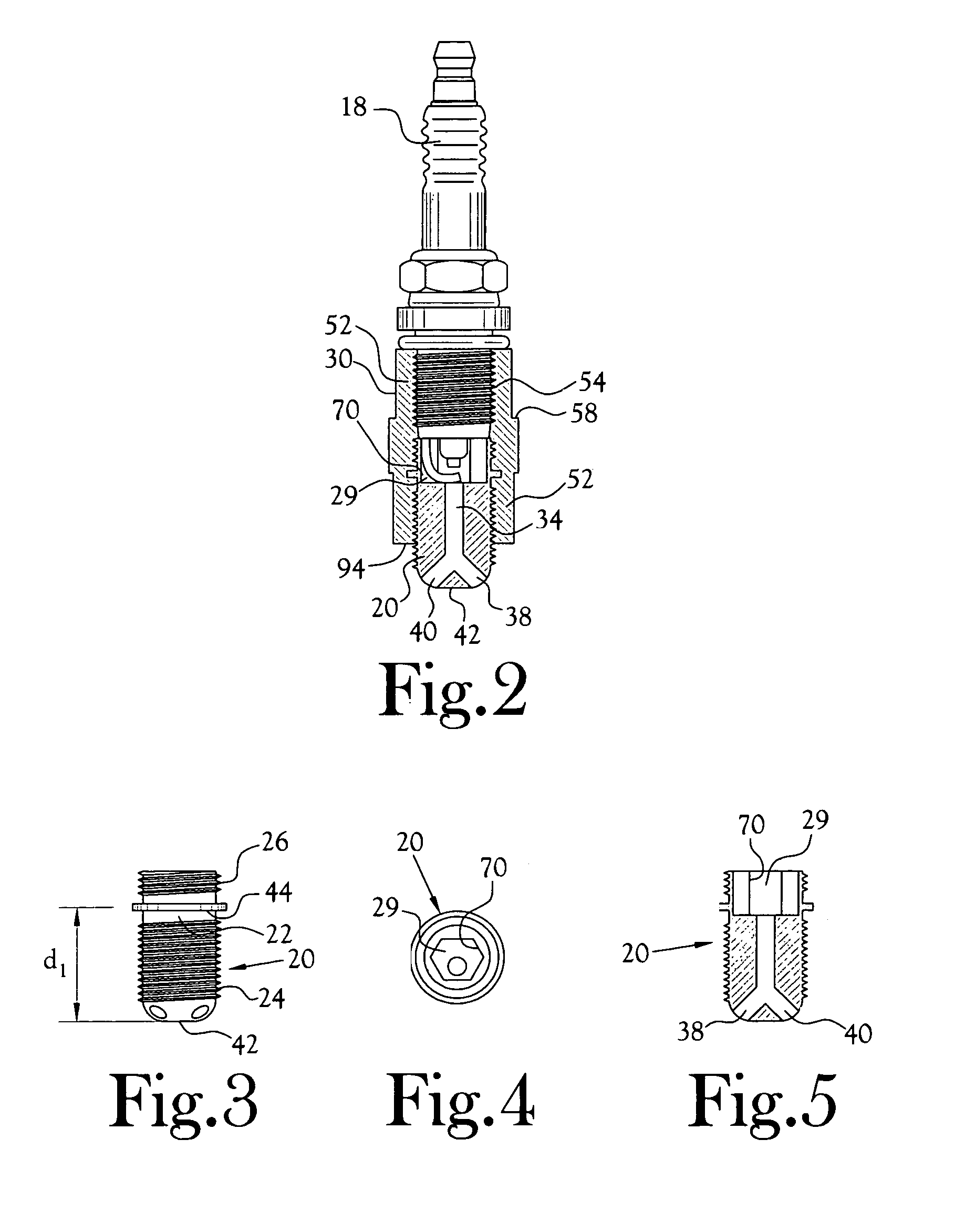
[0008]In accordance with one aspect of the present invention, the efficiency of operation of a common prior art combustion engine is enhanced by ignition of the air / fuel mixture present in a cylinder of the engine near the top dead center of the compression stroke of a piston disposed within the cylinder, by means of a flame which originates in a remote combustion chamber disposed externally of the cylinder of the engine and between the common spark plug and the interior of the cylinder of the engine and propagated into the cylinder in the form of at least one and preferably two or more flame fronts. In a preferred embodiment, one flame front is directed into the cylinder adjacent the intake port of the cylinder and the other is directed over generally the central area of the piston head disposed in the cylinder.

Problems solved by technology

Moreover, spark ignition requires significant time to achieve smooth and nearly complete combustion of the fuel / air mixture, thereby requiring relatively high octane ratings of the fuel, ignition in advance of optimum timing, and resultant generation of excessive pollutants.

Method used


Image

  • Spark ignition modifier module and method
  • Spark ignition modifier module and method
  • Spark ignition modifier module and method

Examples


Embodiment Construction

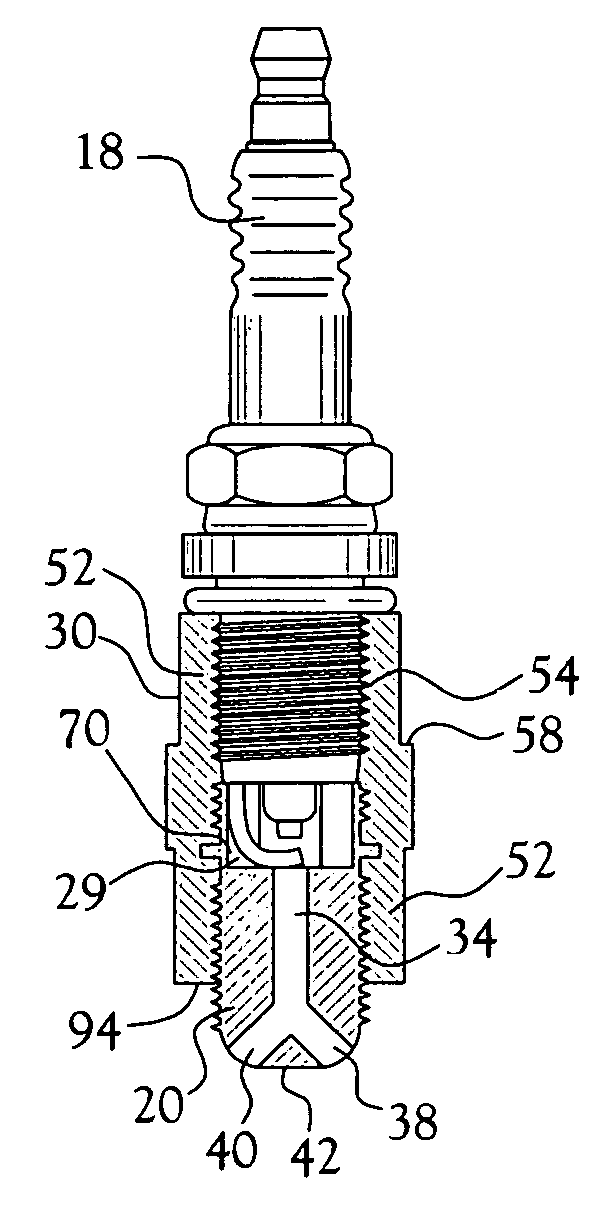
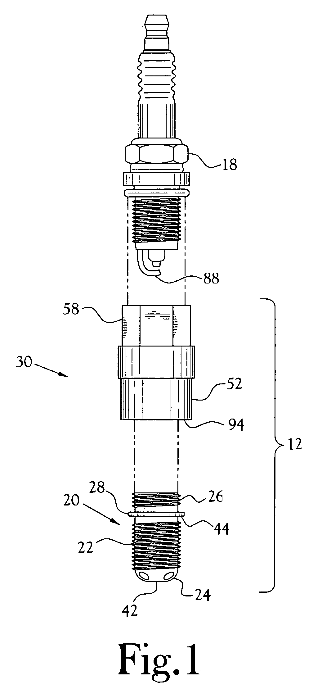
[0024]In one embodiment of the present invention, there is provided a two-element module 12 designed to be interposed between the existing threaded spark plug port 14 to an engine block 16 and the spark plug 18 itself. The first element of the module is designated as a flame cone 20 and comprises a first, generally cylindrical body portion 22 including a first end portion 24 and an opposite second end portion 26. A circumferential flange 28 projects outwardly of the outer circumference of the body portion intermediate the first and second end portions to define the demarcation between the first and second end portions of the flame cone.

[0025]The first end portion 24 of the flame cone element is externally threaded to be threadably received within an existing internally threaded spark plug port 14 of an engine block 16. The second end portion 26 is externally threaded to be threadably received within a first end 52 of a second element 30 (designated a connector) of the module. The fl...


PUM


Abstract

A multi-part module including a flame cone and a connector adapted to be interposed between the normal spark plug port in an internal combustion engine block and a spark plug suitable for use with the engine in question. In the method, a quantity of fuel / air mixture is captured in a chamber which also houses the electrode of a spark plug. Upon generation of a spark from the spark plug, this quantity of fuel / air mixture ignites, generating a flame which propagates through one or more channels in a flame cone interposed between the spark plug and the cylinder of the engine and exits into the cylinder through multiple directionally oriented ports, whereupon the flame fronts rapidly ignite substantially all the fuel / air mixture held within the cylinder.

Description

CROSS-REFERENCE TO RELATED APPLICATIONS[0001]Not ApplicableSTATEMENT REGARDING FEDERALLY SPONSORED RESEARCH OR DEVELOPMENT[0002]Not ApplicableBACKGROUND OF THE INVENTION[0003]The modern internal combustion engine such as used in automobiles, trucks, and like vehicles has been refined and improved over the years since its inception. One aspect of this type engine, namely the igniting of the air / fuel mixture in the combustion chambers has been largely ignored.[0004]In combustion engines, the spark plug is depended upon to ignite a chemically correct air / fuel mixture (approx. 15:1) in a large cylinder head. To accomplish this task, the ignition is started before the piston reaches the top dead center of the compression stroke. This is known as the spark advance and can be as much as 40 degrees before the top of the compression stroke. It therefore may be recognized that any work that is started before the end of the compression stroke is negative and is dissipated as heat in the engine...

Claims


Application Information

Patent Timeline
Patent Type & Authority Patents(United States)
IPC IPC(8): F02B19/12
CPCF02B19/1014F02B19/12Y02T10/125Y02T10/12
Inventor GAGLIANO, HOWARDSATTERFIELD, MARION M.
Owner SMARTPLUG
Learn More