
Articulated seal

a technology of articulation and seals, applied in the direction of engine seals, shafts and bearings, rotary bearings, etc., can solve the problems of affecting the wear pattern and the useful life of seals, the prior use of air pressure to seal both liquid and solid materials has not been entirely satisfactory, and the wear pattern is not uniform

Inactive Publication Date: 2006-08-15
INPRO INC
View PDF5 Cites 49 Cited by
  • Summary
  • Abstract
  • Description
  • Claims
  • Application Information

AI Technical Summary

Problems solved by technology

The problem is especially acute in air barrier seals where the shaft to bore misalignment is maximized.
Prior uses of air pressure to seal both liquid and solid materials have not been entirely satisfactory because of the inherent tight clearance necessary to create the required air pressure in the seal greater than the pressure of the product on the other side of the seal.
Shaft misalignment is also a problem with contact seals with the contact resulting in greater wear due to the misalignment.
Abrasiveness of the product also affects the wear pattern and the useful life of the seals.

Method used


Image

  • Articulated seal
  • Articulated seal
  • Articulated seal

Examples


Embodiment Construction

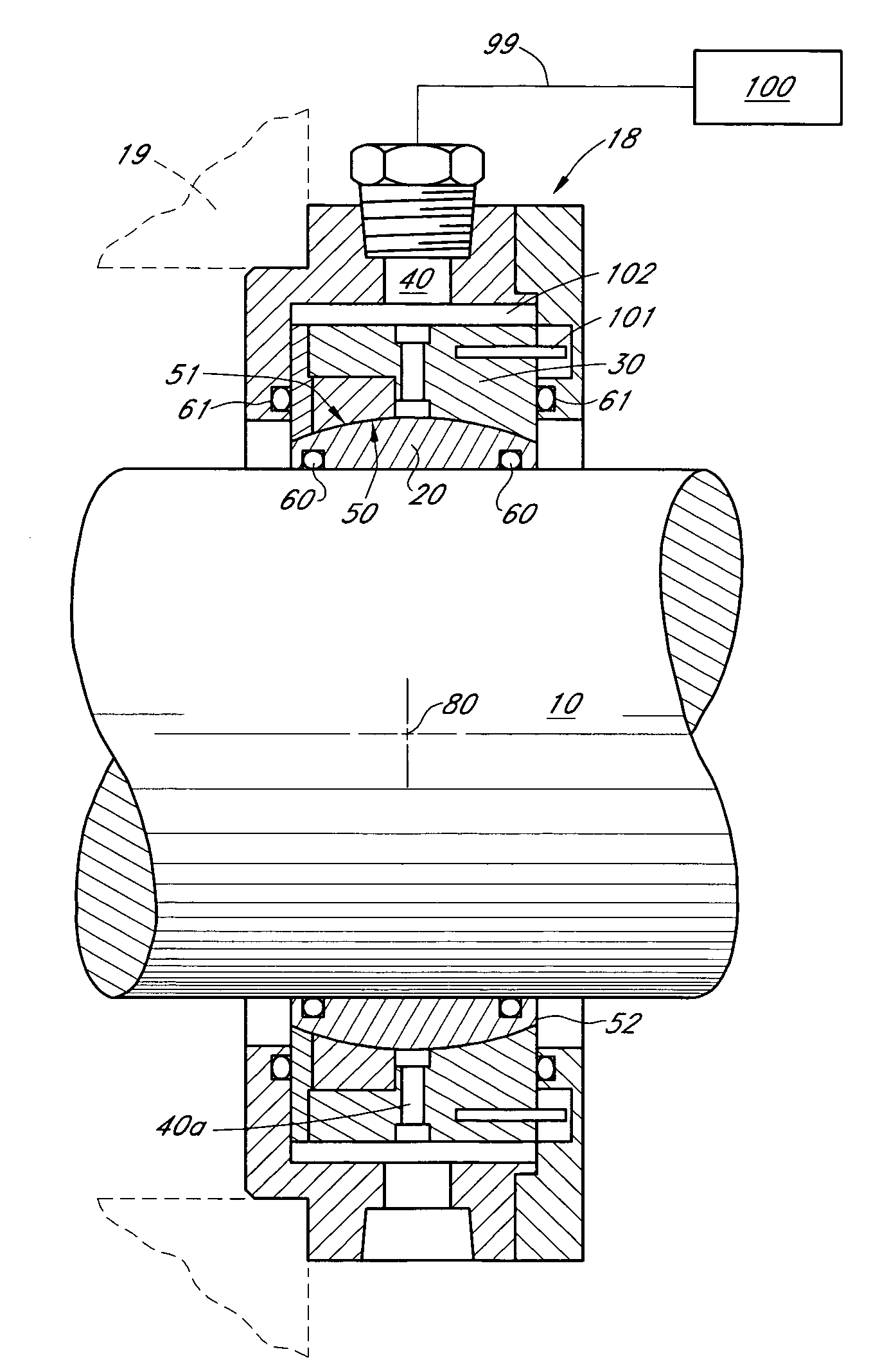
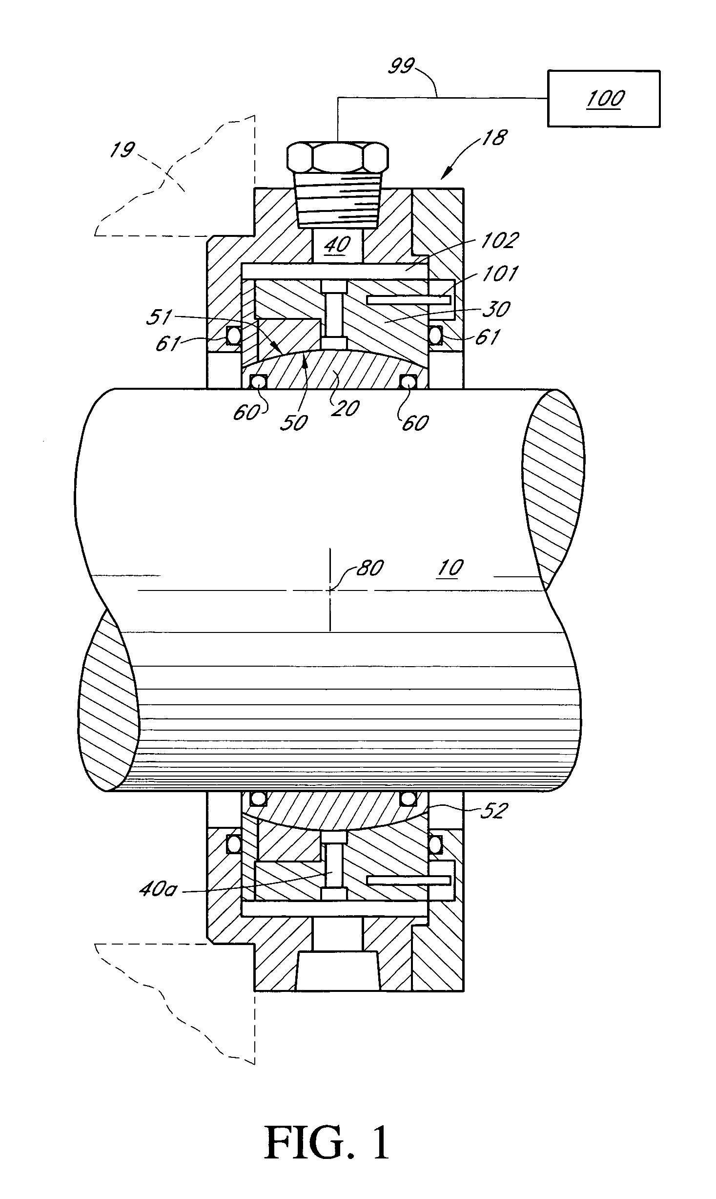
[0012]FIG. 1 shows the bearing isolator 18, mounted on a shaft 10, the shaft 10 extends through the isolator 18 and the housing 19, and a source of gas or fluid 100 which may include water or lubricant and conduit 99. The novel isolator seal of this invention is shown with the stator 30. The rotor 20 is rotatively affixed to the shaft 10 by means by a frictional seal 60. The rotor 20 follows the rotational movement of the shaft 10 because of the frictional engagement of the seals 60. The passages 40 and 40a are as shown but will not be described in detail here because such description is already understood by those skilled in the art.

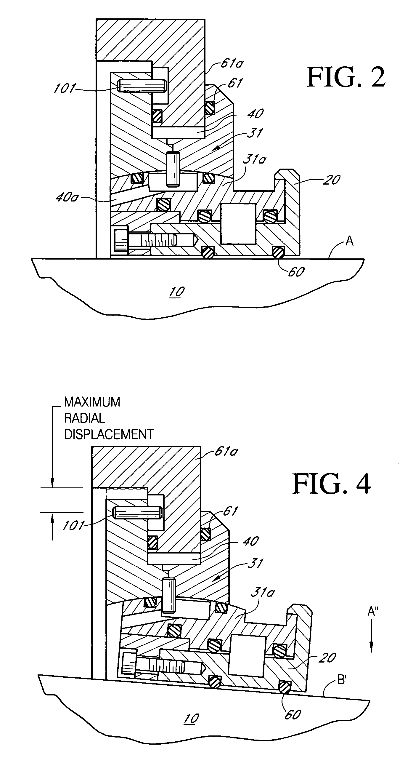
[0013]The basic novelty of this invention includes the utilization of a pair of spherical surfaces, faces or interfaces 50 and 51 to create a self aligning tight radial clearance between the rotor 20 and the stator 30 prior to and after use. This clearance 52 is maintained at a constant value even as the shaft 10 becomes misaligned during use. Various a...


PUM


Abstract

A combination of a bearing isolator shaft and housing with a stator member affixed to said housing, a plurality of spherical faces or interfaces between said rotor and said stator, said spherical interfaces having identical center points between said shaft and radially responsive to each other as radial movement of said rotor member occurs whereby said spherical surfaces are continually intermeshed and maintained at a constant distance from each other.

Description

BACKGROUND OF THE INVENTION[0001]For years there have been a multitude of attempts and ideas for providing a satisfactory seal when a shaft is angularly misaligned from the bore and the shaft runs out.[0002]The problem is especially acute in air barrier seals where the shaft to bore misalignment is maximized. The solution requires both the tight running clearance between the seal members and the stationary member and a loose running clearance for adjustment for operational conditions especially misalignment of the shaft with respect to the stator or stationary member.[0003]Prior uses of air pressure to seal both liquid and solid materials have not been entirely satisfactory because of the inherent tight clearance necessary to create the required air pressure in the seal greater than the pressure of the product on the other side of the seal.[0004]This is to say that to ensure proper sealing, i.e. the tighter the seal less volume of air is required to maintain the seal against the ext...

Claims


Application Information

Patent Timeline
IPC IPC(8): F16C23/04F16J15/447
CPCF16C23/045F16C33/74F16J15/4478F16J15/4474F16J15/3224
Inventor ORLOWSKI, DAVID C.HOEHLE, NEIL F.
Owner INPRO INC
Learn More