
Adjustable magnetic resistance mechanism for upright bikes

a magnetic resistance mechanism and upright bike technology, applied in the direction of gymnastic exercise, sport apparatus, cardiovascular exercise devices, etc., can solve the problems of time-consuming and laborious work, and the gap between the magnetic resistance device and the flywheel can be too far to adjust, so as to achieve the effect of convenient adjustmen

Inactive Publication Date: 2006-07-18
LIN MICHAEL
View PDF8 Cites 33 Cited by
  • Summary
  • Abstract
  • Description
  • Claims
  • Application Information

AI Technical Summary

Benefits of technology

[0006]The primary object of the present invention is to provide a magnetic resistance mechanism wherein the gap between the magnet unit and the flywheel is easily to be adjusted.

Problems solved by technology

In other words, after the upright bikes are assembled form the production lines, special persons are then adjust the gap of each upright bike one by one, and this is a time-consuming job.
Besides, during producing the frames of the bikes, holes for receiving shaft of flywheel might not be drilled at the desired positions and the support frame 5 or frame 2 might not be welded at correct position, so that the gap between the magnetic resistance device and the flywheel can be too far to adjust.

Method used


Image

  • Adjustable magnetic resistance mechanism for upright bikes
  • Adjustable magnetic resistance mechanism for upright bikes
  • Adjustable magnetic resistance mechanism for upright bikes

Examples


Embodiment Construction

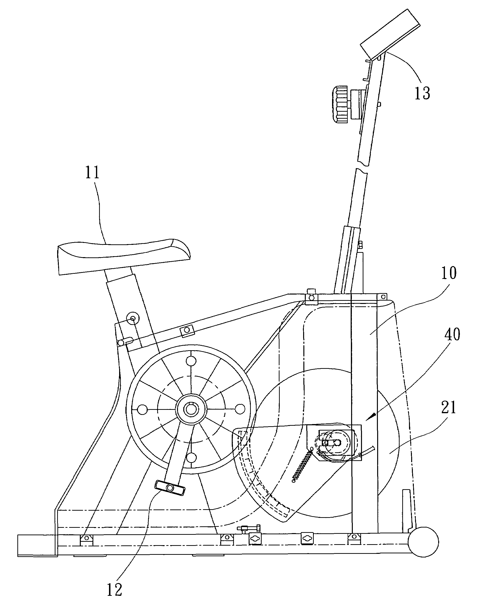
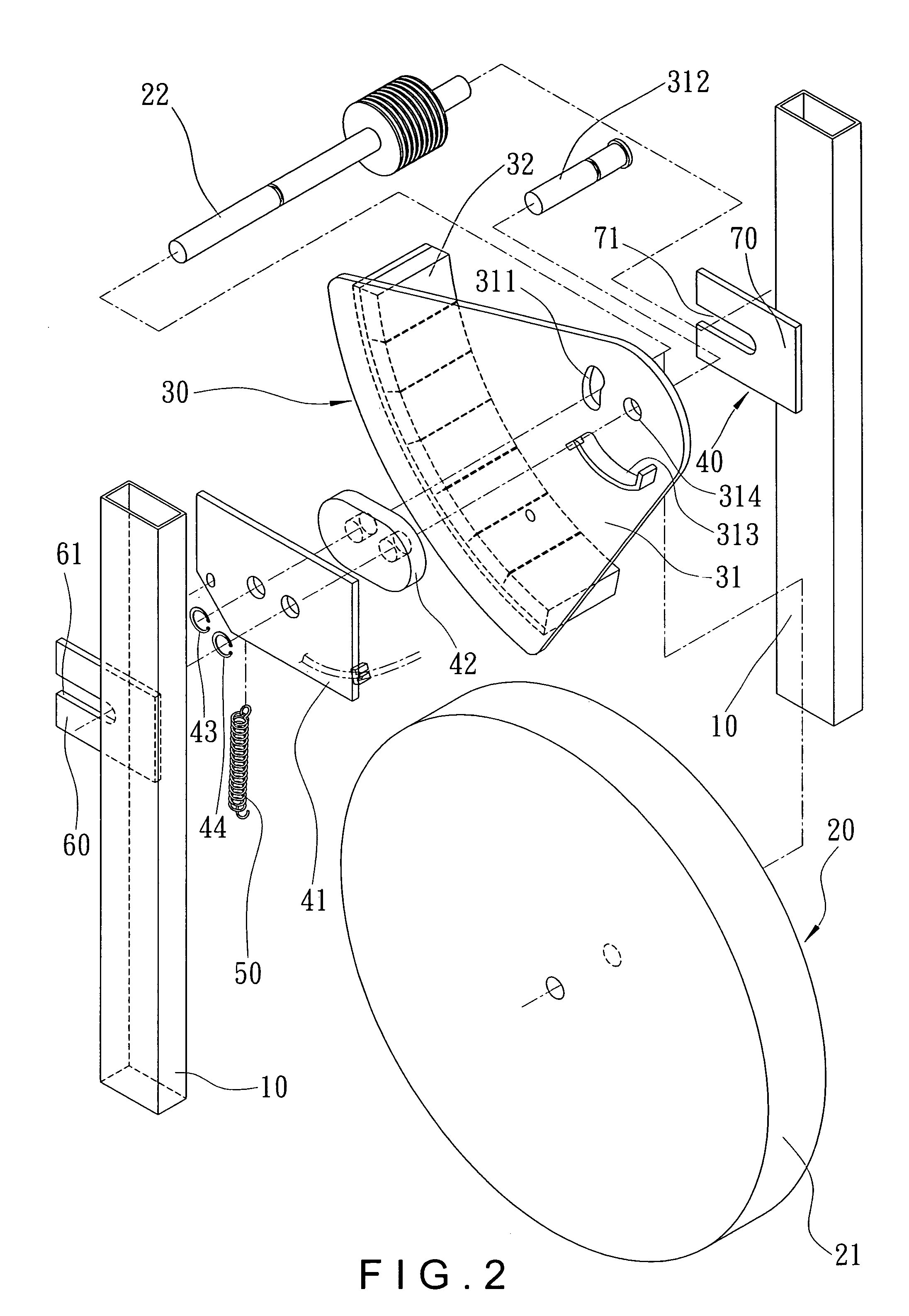
[0014]Referring to FIGS. 2, 3, 4, 5 and 7, the magnetic resistance upright bike of the present invention comprises a bicycle frame including two upright posts 10 between which a flywheel 21 is rotatably connected. A handle 13 is connected to a top of a handle post and a seat 11 is connected to a seat post. A driving wheel which can be rotated by operating a crank to which two pedals 12 are connected. A user can sit on the seat 11 and rotate the crank to rotate the flywheel 21. An adjustable magnetic resistance mechanism includes a flywheel assembly 20 and a magnetic resistance device 30. The flywheel assembly 20 includes the flywheel 21 and a shaft 22 extends through a center of the flywheel 21. Two ends of the shaft 22 are supported in two respective horizontal slots 61, 71 of two support plates 60, 70 which are connected to two upright posts 10 of the upright bike.

[0015]The magnetic resistance device 30 includes an adjustment board 31 and a magnet unit 32 which includes a pluralit...


PUM


Abstract

An adjustable magnetic resistance mechanism of an upright bike includes a fan-shaped adjustment board which is pivotably connected to the bike's frame and a magnet unit is connected to a distal end of the adjustment board. A connection board is connected to the adjustment board and a shaft of the flywheel extends through a curve slot of the adjustment board. Two ends of the shaft are supported on two support plates on two upright posts of the upright bike. An axle extends through a pivot hole in the adjustment board and the connection board. A resilient member is connected between the connection board and the adjustment board. The adjustment board is pivoted about the axle to adjust the gap between the flywheel and the magnet unit on the adjustment board.

Description

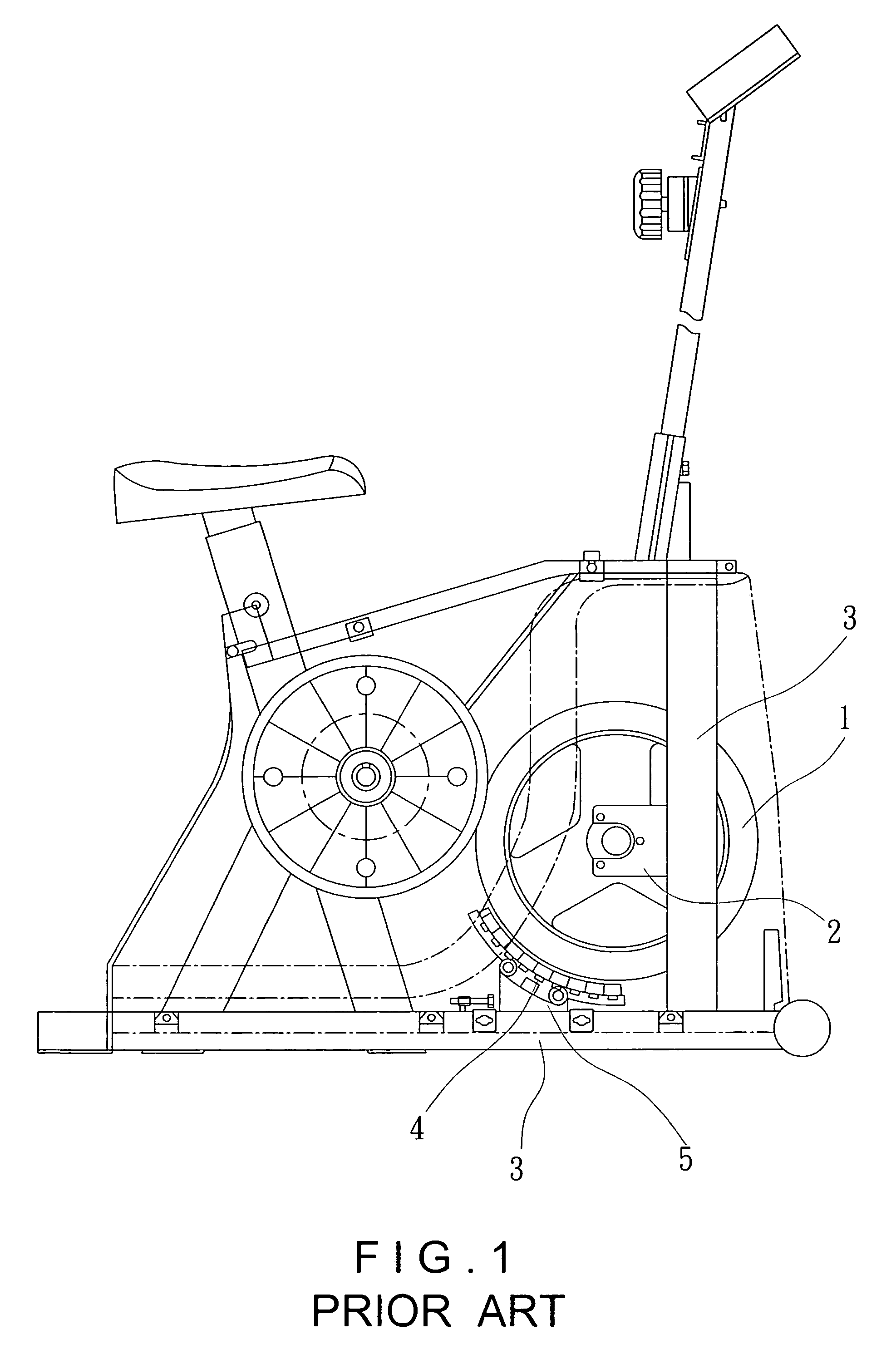
FIELD OF THE INVENTION[0001]The present invention relates to an adjustable magnetic resistance device and a flywheel, both of which are connected to an adjustment board by two individual shaft and axle so that the gap between the magnetic resistance device and the flywheel is conveniently adjusted.BACKGROUND OF THE INVENTION[0002]A conventional upright bike with magnetic resistance device is shown in FIG. 1 and generally includes two upright posts 3 on a horizontal base 3 of the bike and a flywheel 1 is installed between the two upright posts 3 by a frame 2. A magnetic resistance device 4 is connected above the horizontal base 3 by a support frame 5 and a proper gap is defined between the magnetic resistance device 4 and the flywheel 1 so as to generate a desired resistance to the flywheel 1. The gap has to be checked by professional persons after the magnetic resistance device 4 and the flywheel 1 are installed. In other words, after the upright bikes are assembled form the product...

Claims


Application Information

Patent Timeline
Patent Type & Authority Patents(United States)
IPC IPC(8): A63B22/06
CPCA63B21/0051A63B22/0605A63B21/225
Inventor CHEN, MING NAN
Owner LIN MICHAEL
Learn More