
Input device including a scroll wheel assembly for manipulating an image in multiple directions

a technology of input device and scroll wheel, which is applied in the direction of input/output for user-computer interaction, instruments, computing, etc., can solve the problems of inconvenient scrolling, small display screen and/or poor hand-eye coordination, and inability to perform additional pointing tasks which are more time-consuming and mentally intensive, etc., to achieve convenient scrolling and simple thumb or finger movements. , the effect of scrolling

Inactive Publication Date: 2006-05-09
MICROSOFT TECH LICENSING LLC
View PDF61 Cites 54 Cited by
  • Summary
  • Abstract
  • Description
  • Claims
  • Application Information

AI Technical Summary

Benefits of technology

The present invention allows users to conveniently scroll through screen images in multiple directions using simple thumb or finger movements. This is achieved through a scroll wheel assembly that includes a rotatable member attached to a device for sensing and encoding rotational motion. The encoded rotational motion causes scrolling of an image on a display screen along an axis. The scroll wheel assembly can be used in various applications where multidirectional scrolling is desired or useful. Additionally, the invention includes an input device with an actuator that can generate signals in response to pressure on different parts of the actuator, allowing for additional screen functions. The actuator is positioned within the input device, and at least part of it protrudes through an opening in the housing. The actuator is rotatable with respect to the housing, and can rotate through multiple complete revolutions. The technical effects of the invention include improved user experience and more efficient and convenient screen navigation.

Problems solved by technology

Locating the scroll bar can be very difficult for people with bad eyesight, small display screens and / or poor hand-eye coordination.
Even if the size of the horizontal scroll bar and / or the screen resolution can be adjusted, the user must nevertheless perform additional pointing tasks which are more time-consuming and mentally intensive than simply rotating a wheel or pushing a button.
However, this arrangement has drawbacks.
The smaller sized scroll wheels make the scrolling more difficult to control.
Additionally, the location of the horizontal scroll wheel can be inconvenient for effective control.
Further, with this design, it might be difficult for some users to easily reach and manipulate both of the wheels.

Method used


Image

  • Input device including a scroll wheel assembly for manipulating an image in multiple directions
  • Input device including a scroll wheel assembly for manipulating an image in multiple directions
  • Input device including a scroll wheel assembly for manipulating an image in multiple directions

Examples


Embodiment Construction

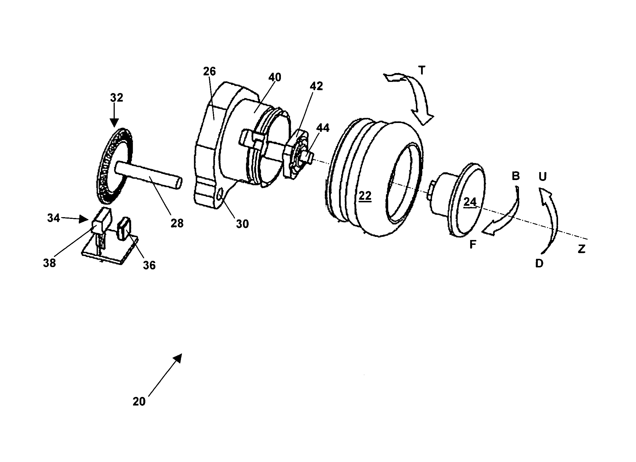
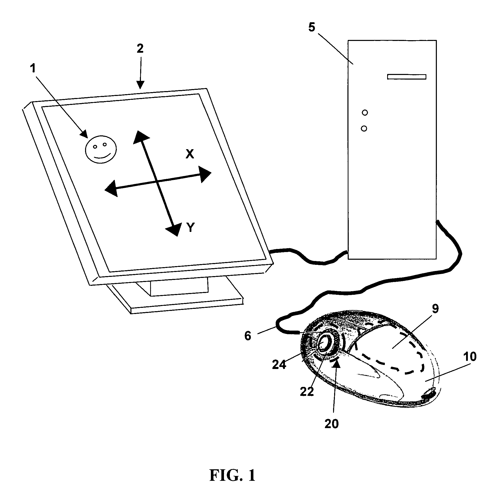
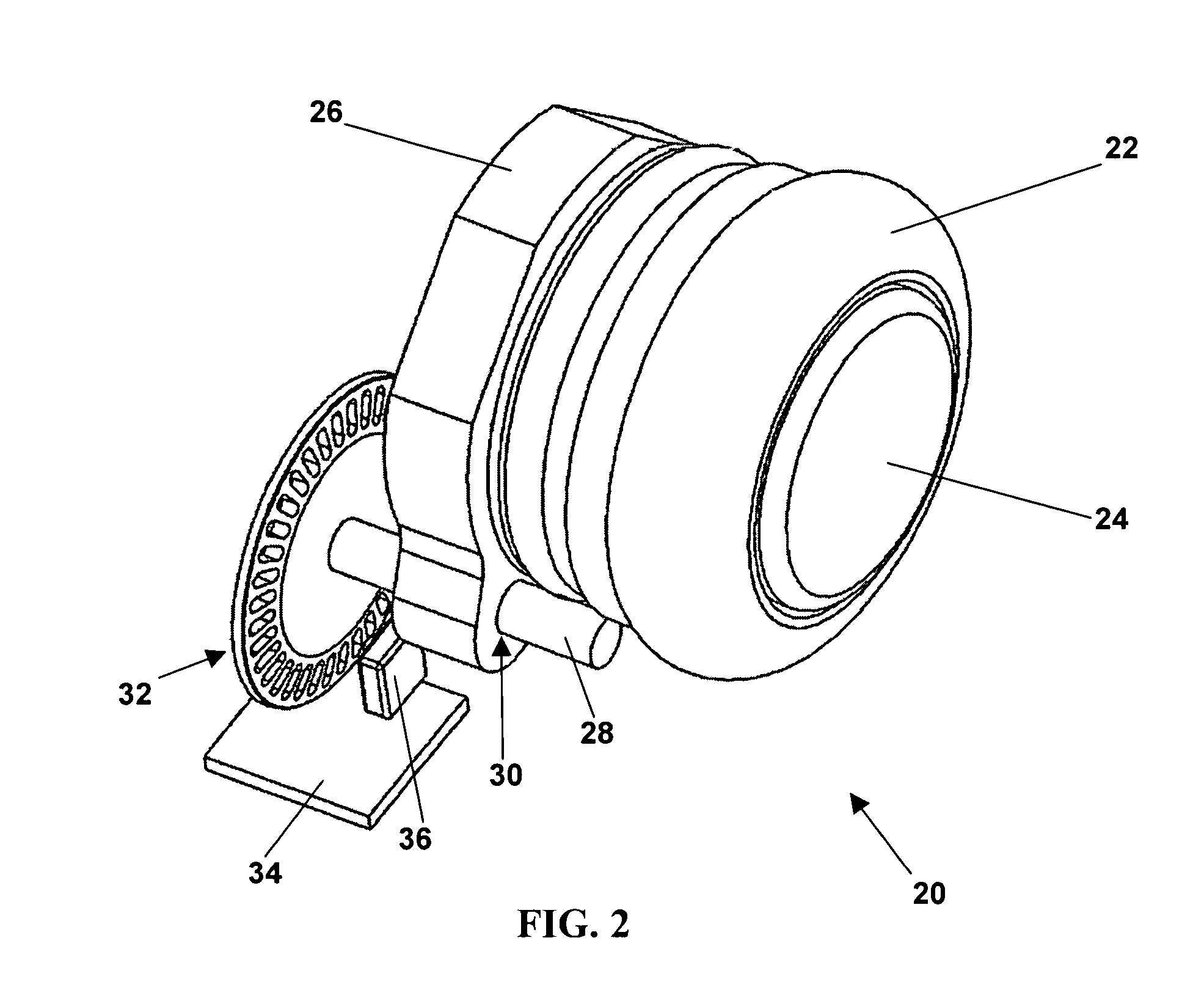
[0018]FIGS. 1–7 illustrate an exemplary embodiment of a scroll wheel assembly 20 of the present invention as adapted for use in an input device such as computer mouse 10. For convenience, the invention will first be described with reference to the mouse 10 of FIG. 1. However, the invention is not so limited, and as set forth in detail below, can be used in multiple devices and in multiple configurations. Scroll wheel assembly 20 includes a rotatable member 22 and a button 24. Rotatable member 22 will generally (though not necessarily) be round. For convenience, rotatable member 22 will hereinafter be referred to as a scroll wheel. However, and as set forth herein, rotatable member 22 could also be used as a “zoom” wheel, a volume control, or for other purposes. By rotating scroll wheel 22, an image 1 (which may be text, graphics, a combination of text and graphics, or other displayable information) on the screen of display 2 may be moved up or down along a Y-axis. By pressing button...


PUM


Abstract

A scroll wheel assembly includes a rotatable member. Encoded rotation of the rotating member causes scrolling of an image on a display screen along an axis. An actuator is located within the rotational member. Pressure on different parts of the actuator causes scrolling of the image in opposing directions along a second axis. Pressure upon additional parts of the actuator can provide additional screen functions. Functions and commands caused by manipulation of the rotatable member or actuator may also be programmable.

Description

FIELD OF THE INVENTION[0001]The present invention relates to an input device including an assembly for moving an image in multiple directions on a display screen. More particularly, the present invention relates to a scroll wheel assembly that, when part of a peripheral or integral input device that is operatively connected to a host computer, can move an image in multiple axes relative to the display screen.BACKGROUND OF THE INVENTION[0002]The viewable contents of a computer file, such as a text document, spreadsheet, digital photograph, Web page, or other image rendered on a conventional display screen, may possess a size exceeding the viewable boundaries of the display screen. To address this issue, an individual may utilize a scrolling method to scroll the image relative to the display screen. Scrolling, as used herein and as is known in the art, describes the movement of an image relative to a display screen in a particular direction. For example, “scrolling down” generally des...

Claims


Application Information

Patent Timeline
Patent Type & Authority Patents(United States)
IPC IPC(8): G09G5/00G06F3/02G06F3/033G06F3/048G09G5/08
CPCG06F3/0213G06F3/0312G06F3/0485G06F3/03543G06F3/0362G06F3/0338
Inventor ADAMS, ADITHA M.BATHICHE, STEVEN N.FISHER, STEVEN W.GARCIA, GINOLINDHOUT, DAANMUSS, TIMOTHY MICHAELNEWTON, MARK
Owner MICROSOFT TECH LICENSING LLC
Learn More