
Telescoping box adapter

a technology for adapters and telescopic boxes, which is applied in the direction of machine supports, electrical apparatus casings/cabinets/drawers, coupling device connections, etc., can solve the problems of unsightly electrical outlets that detract from the attractiveness of the building, the purpose of the weatherproof cover, and the bubble cover extending this unsightly distance from the wall

Active Publication Date: 2006-05-02
ARLINGTON INDS
View PDF11 Cites 64 Cited by
  • Summary
  • Abstract
  • Description
  • Claims
  • Application Information

AI Technical Summary

Benefits of technology

[0012]e) The telescoping box adapter provides a truly weatherproof cover for electrical boxes, thereby enabling electrical box installations using the adapter to meet the National Electrical Code for weatherproof electrical boxes.
[0013]These and other objects and advantages of the present invention will be better understood by reading the following description along with reference to the drawings.

Problems solved by technology

Although the current while-in-use electrical box covers adequately cover the electrical outlet, they suffer from several disadvantages.
For those situations in which there are no electrical cords plugged into the outlet, the openings for the electrical cords, which are open at all times, provide open passageways for allowing weather to enter the openings and thereby defeat the purpose of the weatherproof cover.
This protrusion from the wall places the cover in a position where it can be easily impacted by outdoor power equipment, vehicles and the like and also creates an unsightly electrical outlet that detracts from the building's attractiveness.
Additionally, the bubble cover extends this unsightly distance from the wall regardless of whether or not an electrical cord is plugged into the outlet.

Method used


Image

  • Telescoping box adapter
  • Telescoping box adapter
  • Telescoping box adapter

Examples


Embodiment Construction

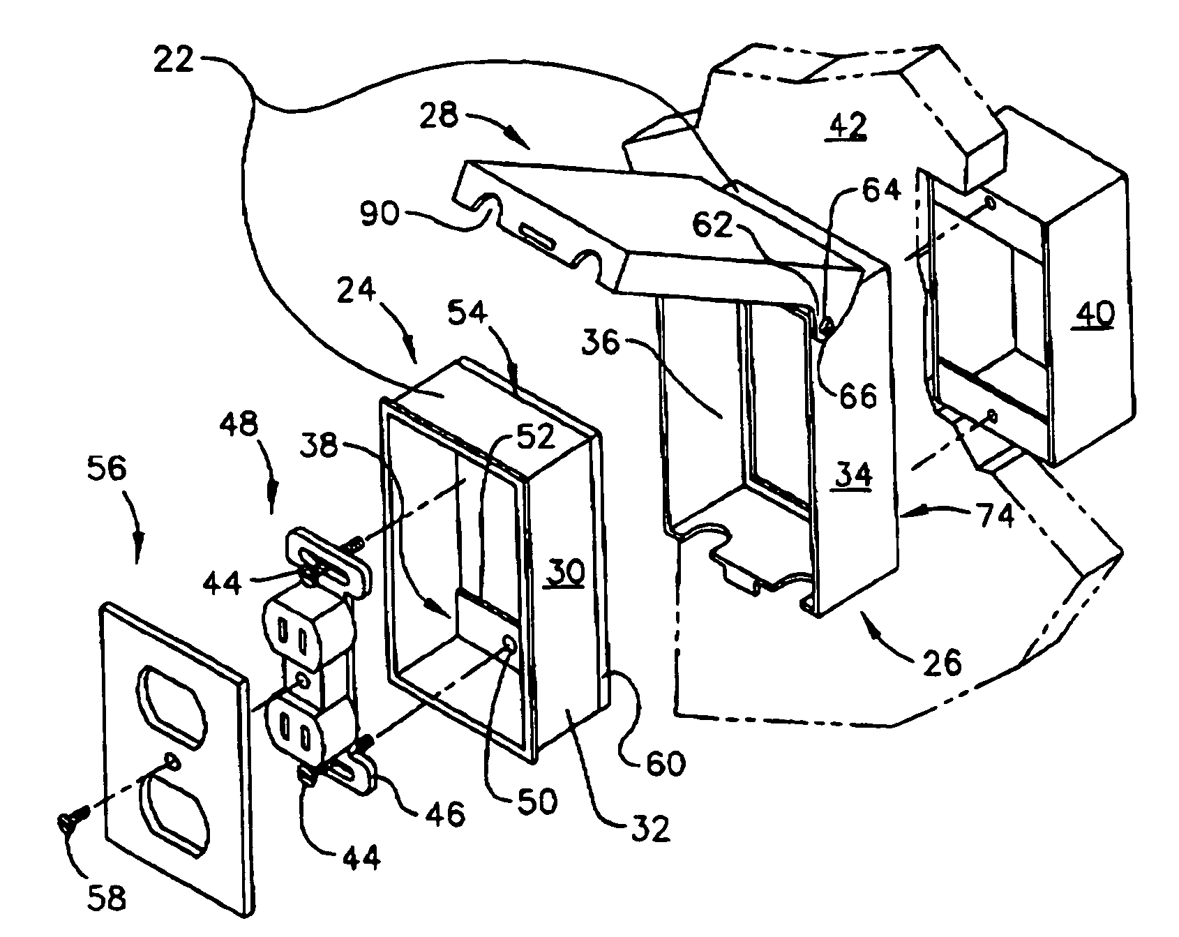
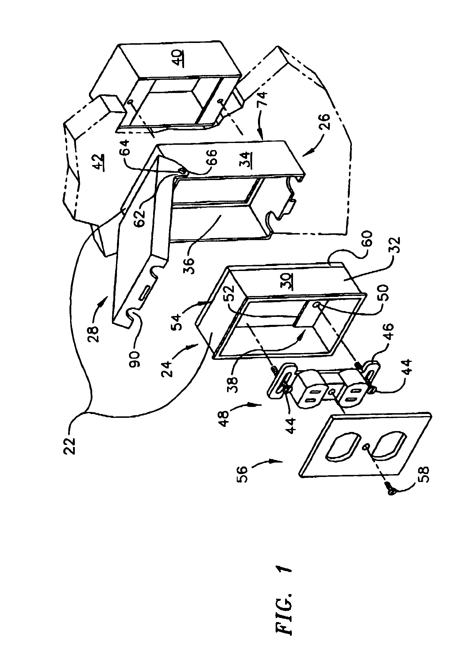
[0038]With reference to FIG. 12, a first embodiment is shown of a telescoping box adapter according to the present invention. The first embodiment is a two-tier telescoping box adapter 22 that includes a first frame member 24, a second frame member 26 slideable with respect to the first frame member 24, and a cover member 28 secured to the second frame member 26.

[0039]Referring to FIG. 1, the first frame member 24 includes sidewalls 30 having an outer periphery 32. The second frame member 26 includes sidewalls 34 having an inner periphery 36. A fastening arrangement 38 is provided on the first frame member 24 for securing the first frame member 24 to an electrical box 40. As shown in FIG. 1, the two-tier telescoping box adapter 22 may be secured to an electrical box 40 that is mounted to a wall 42. The telescoping box adapter 22 is secured to the electrical box 40 by fasteners 44 threaded through the ears 46 of an electrical device 48 and then through apertures 50 in extensions 52 f...


PUM


Abstract

A telescoping box adapter that enables a user to adjust the enclosure on an electrical box from a compressed to an expanded configuration. The telescoping box adapter includes a first frame member that is secured to an electrical box. A second frame member having sidewalls slightly larger than the first frame member is slideable with respect to the first frame member. Additional frame members can be provided with successively larger sidewalls thus making each additional frame member slideable with respect to the next smaller frame member. A cover is secured to the outermost frame member and is movable from an open to a closed position. Sliding the outermost frame member fully forward adjusts the box adapter to a fully expanded configuration forming an expanded enclosure therein. Sliding the outermost frame member fully rearward adjusts the box adapter to a fully compressed configuration forming a compressed enclosure therein.

Description

FIELD OF THE INVENTION[0001]This invention relates to covers for electrical outlets and specifically to a novel weatherproof adaptable cover that can be adjusted from an expanded configuration to accommodate an outlet having a plug inserted therein or to a collapsed configuration to accommodate the outlet without an inserted plug.BACKGROUND OF THE INVENTION[0002]Electrical outlets are commonly installed on the exteriors of buildings to provide electrical service for powering outdoor equipment, lights, and similar devices. For those electrical outlets installed on the exterior of a building, the National Electrical Code now requires that each outlet be weatherproof.[0003]The “bubble” outlet covers now in use are of a fixed size and large enough to accommodate electrical cords that are plugged into the outlet. These are commonly called while-in-use covers as the cover protects the outlet and plugs while the outlet is used for providing electrical service to a location remote from the ...

Claims


Application Information

Patent Timeline
Patent Type & Authority Patents(United States)
IPC IPC(8): H01H9/02
CPCH02G3/086Y10S248/906
Inventor GRETZ, THOMAS J.
Owner ARLINGTON INDS
Learn More