
Cooling system for an electric motor

a technology of cooling system and electric motor, which is applied in the direction of electrical equipment, dynamo-electric machines, supports/enclosements/casings, etc., can solve the problems of reducing the ability to air cool the motor, increasing the power density of the motor, and increasing the difficulty of cooling

Active Publication Date: 2006-03-07
CATERPILLAR INC
View PDF108 Cites 121 Cited by
  • Summary
  • Abstract
  • Description
  • Claims
  • Application Information

AI Technical Summary

Benefits of technology

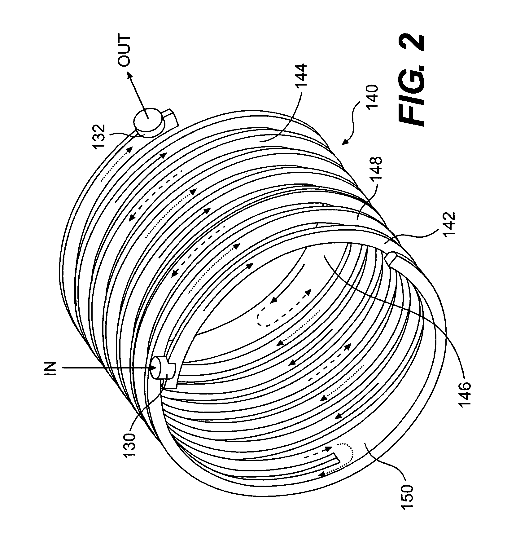
The present patent is about a cooling system for an electric motor. The system includes a cooling duct that is formed between a cooling jacket and a separate component surface, which helps to direct a cooling liquid and draw heat from the motor. The system also includes an inlet and an outlet for the cooling liquid to enter and exit the duct. Additionally, the patent describes an electric motor that has a cooling jacket with a cooling groove that is spiraled, which helps to improve the cooling efficiency of the motor.

Problems solved by technology

Because mobile applications put a premium on smaller size and lower weight, these motors are more power dense and therefore more difficult to cool than their stationary counterparts.
As the size of the motors is decreased, air cooling alone is often insufficient to maintain temperatures of the motors at acceptable levels.
The air may be dusty or dirty, or the motors may become caked in mud, reducing the ability to air cool the motors.
However, casting such passages in housings is difficult and expensive.
Although easier to manufacture than cast interior passages, such a single channel may not provide sufficient cooling for the electric motor, and may provide inconsistent heat zones in the stator.

Method used


Image

  • Cooling system for an electric motor
  • Cooling system for an electric motor
  • Cooling system for an electric motor

Examples


Embodiment Construction

[0015]Reference will now be made in detail to embodiments of the present invention, examples of which are illustrated in the accompanying drawings. Wherever possible, the same reference numbers will be used throughout the drawings to refer to the same or like parts.

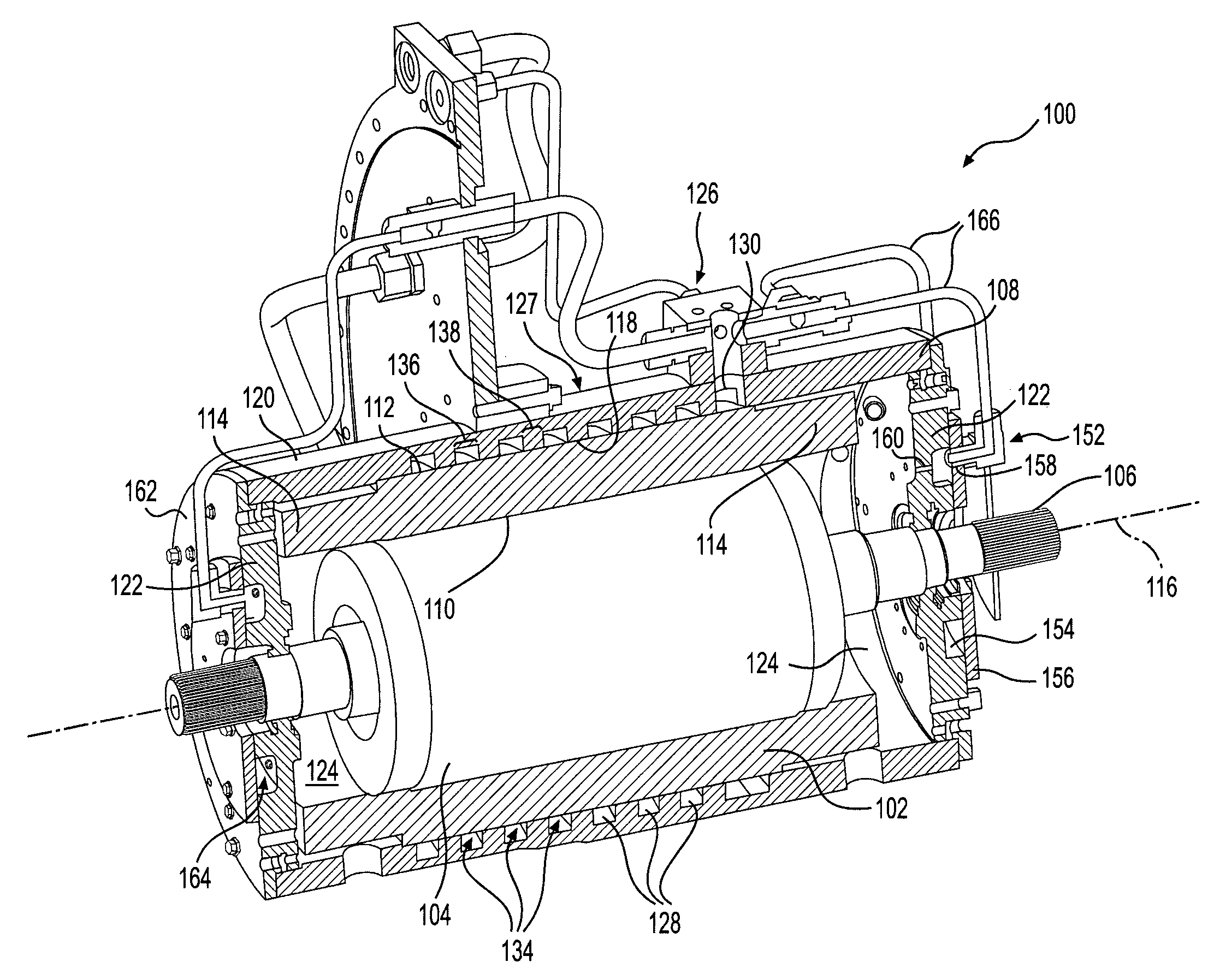
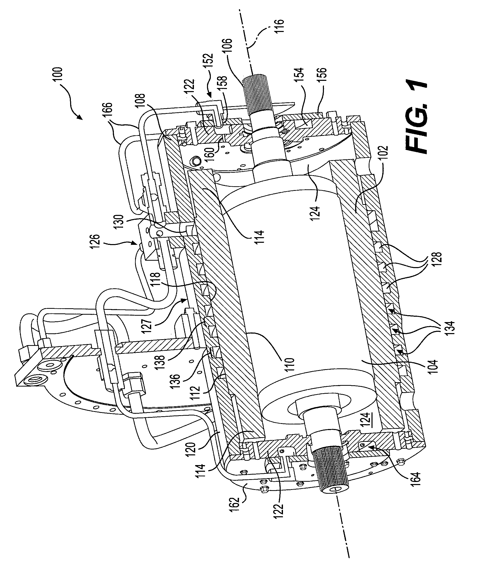
[0016]An exemplary embodiment of an electric motor 100 is illustrated in FIG. 1. The electric motor 100 may be used in any application requiring an electric motor, including a mobile application, such as on a work machine or other vehicle. The electric motor 100 may include a stator 102, a rotor 104, and a shaft 106, all housed in a cooling jacket 108.

[0017]The stator 102 may be formed of a series of thin laminates placed side-by-side, along with windings formed of conducting material. The stator 102 may have a cylindrical shape with an inner surface 110 and an outer surface 112. Each end of the stator 102 may include end windings 114, formed of a series of wound conductive material.

[0018]The rotor 104 may be housed withi...


PUM


Abstract

A cooling system for an electric motor includes a cooling duct formed between a cooling jacket and a separate component surface. The separate component surface may define at least a portion of a wall of the cooling duct. The cooling duct may be configured to direct a cooling liquid along at least a portion of the separate component surface and draw heat from the electric motor. An inlet port may be in fluid communication with the cooling duct. The inlet port may be configured to receive the cooling liquid and to introduce the cooling liquid to the cooling duct. An outlet port may be in fluid communication with the cooling duct.

Description

TECHNICAL FIELD[0001]The present disclosure is directed to a cooling system for an electric motor, and more particularly, to a cooling system for liquid cooling an electric motor.BACKGROUND[0002]Traditionally, electric motors have been used in stationary applications. Because of this, the volume or size of electric motors has not been critical, and sufficient cooling of the electric motors could be achieved by using air, with or without fins, and large motor housings, serving as heat-sinks. More recently, electric motors have been used in mobile applications, such as on automobiles or work machines. Because mobile applications put a premium on smaller size and lower weight, these motors are more power dense and therefore more difficult to cool than their stationary counterparts.[0003]As the size of the motors is decreased, air cooling alone is often insufficient to maintain temperatures of the motors at acceptable levels. Furthermore, because the motors are now often on mobile vehic...

Claims


Application Information

Patent Timeline
Patent Type & Authority Patents(United States)
IPC IPC(8): H02K9/00H02K5/20H02K9/19
CPCH02K9/19H02K5/20H02K5/203
Inventor CRONIN, MICHAEL G.IUND, TREVOR NEAL
Owner CATERPILLAR INC
Learn More