
Fiber splice tray for use in optical fiber hydrophone array

a technology of fiber splice and optical fiber, which is applied in the direction of optics, optical elements, instruments, etc., can solve the problems of degrading light transmission, affecting the mechanical stability of optical fibers, and affecting the quality of optical fibers

Inactive Publication Date: 2005-03-22
GENERAL DYNAMICS MISSION SYST INC
View PDF82 Cites 81 Cited by
  • Summary
  • Abstract
  • Description
  • Claims
  • Application Information

AI Technical Summary

Benefits of technology

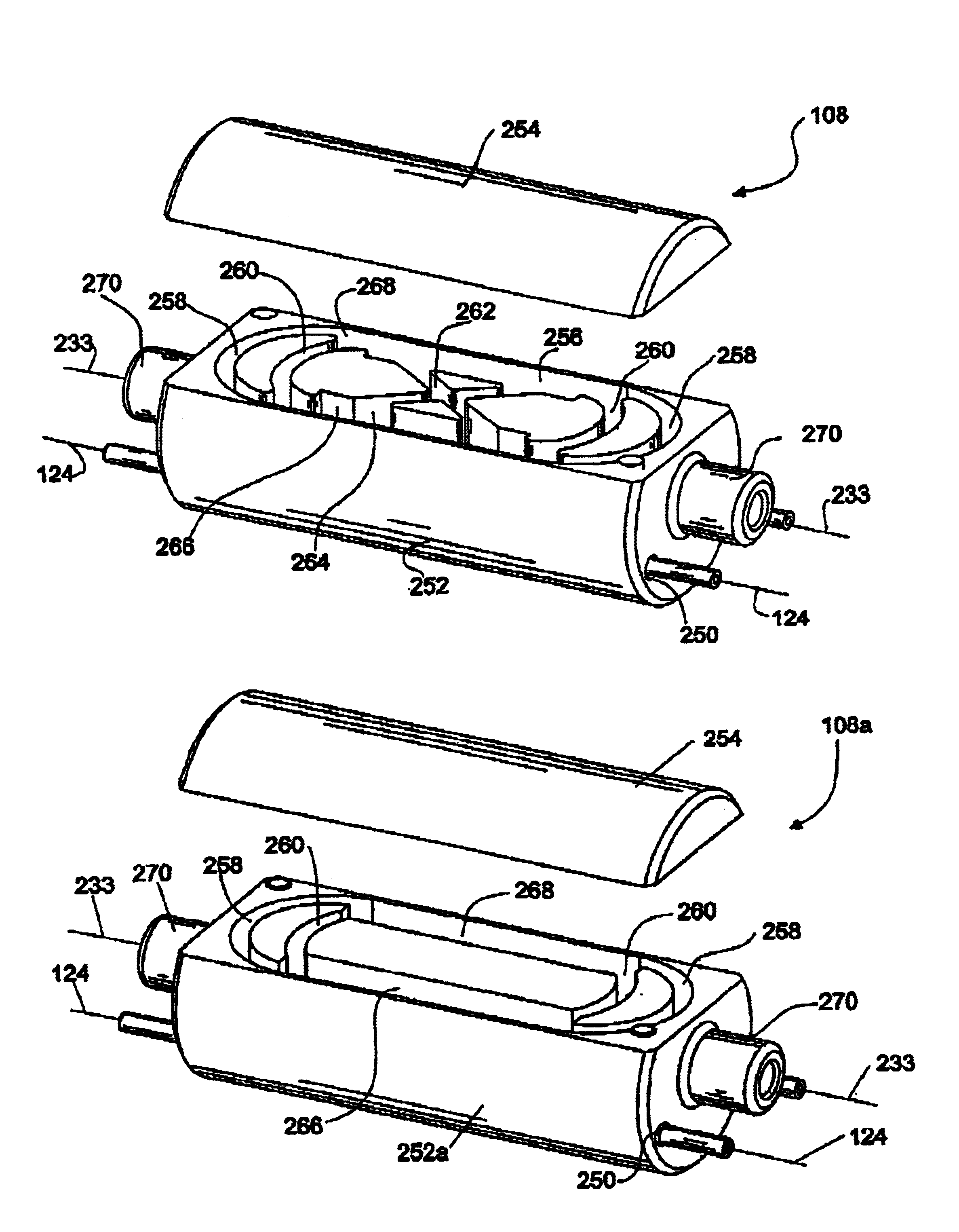
This patent describes a device that connects two optical fiber hydrophone modules together. It uses a special tray with a tiny space where the fibers can be connected without interference from other parts. This makes it easy to build up complex systems made up of multiple modules.

Problems solved by technology

The technical problem addressed in this patent text is the need for reliable means to protect optical fibers in underwater sonar equipment from mechanical failure, including during towing and recovery operations, as well as in the transition areas between modules. Additionally, there is a need for a more efficient and compact way to connect optical fibers in the hydrophone assembly, as well as a reliable splicing technique for integrating prefabricated subcomponents of the hydrophone assembly.

Method used


Image

  • Fiber splice tray for use in optical fiber hydrophone array
  • Fiber splice tray for use in optical fiber hydrophone array
  • Fiber splice tray for use in optical fiber hydrophone array

Examples


Embodiment Construction

[0060]Certain terminology is used herein for convenience only and is not to be taken as a limitation on the invention. For example, words such as forward, aft, upper, lower, left, right, horizontal, vertical, upward, and downward merely describe the configuration shown in the Figures. The components may be oriented in any direction and the terminology, therefore, should be understood as encompassing such variations unless specified otherwise. Also, the scope of the invention is not intended to be limited by the materials or dimensions listed herein, but may be carried out using any materials and dimensions that allow the construction and operation of the hydrophone module.

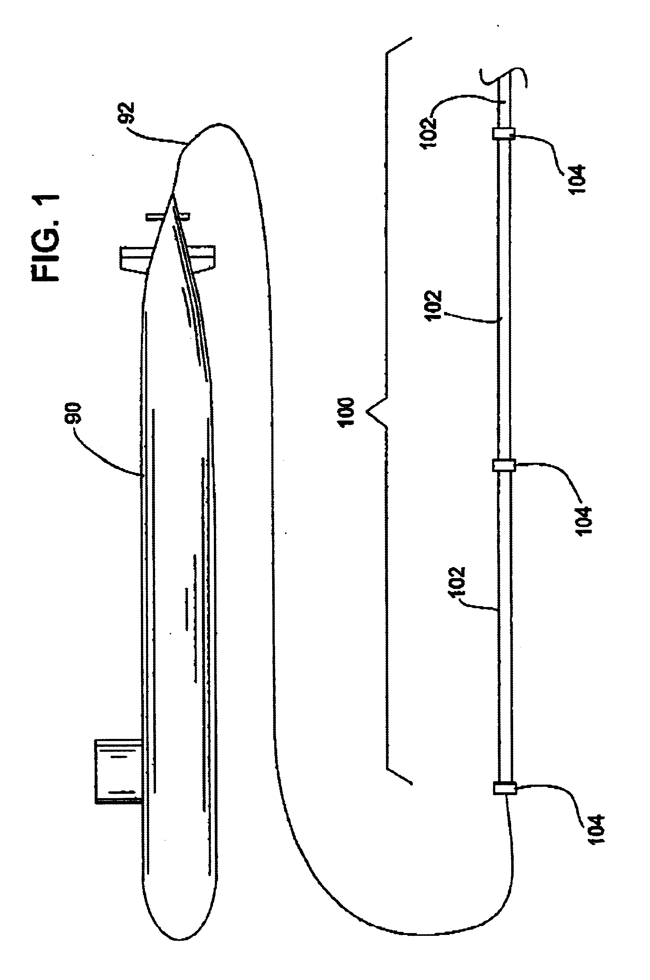
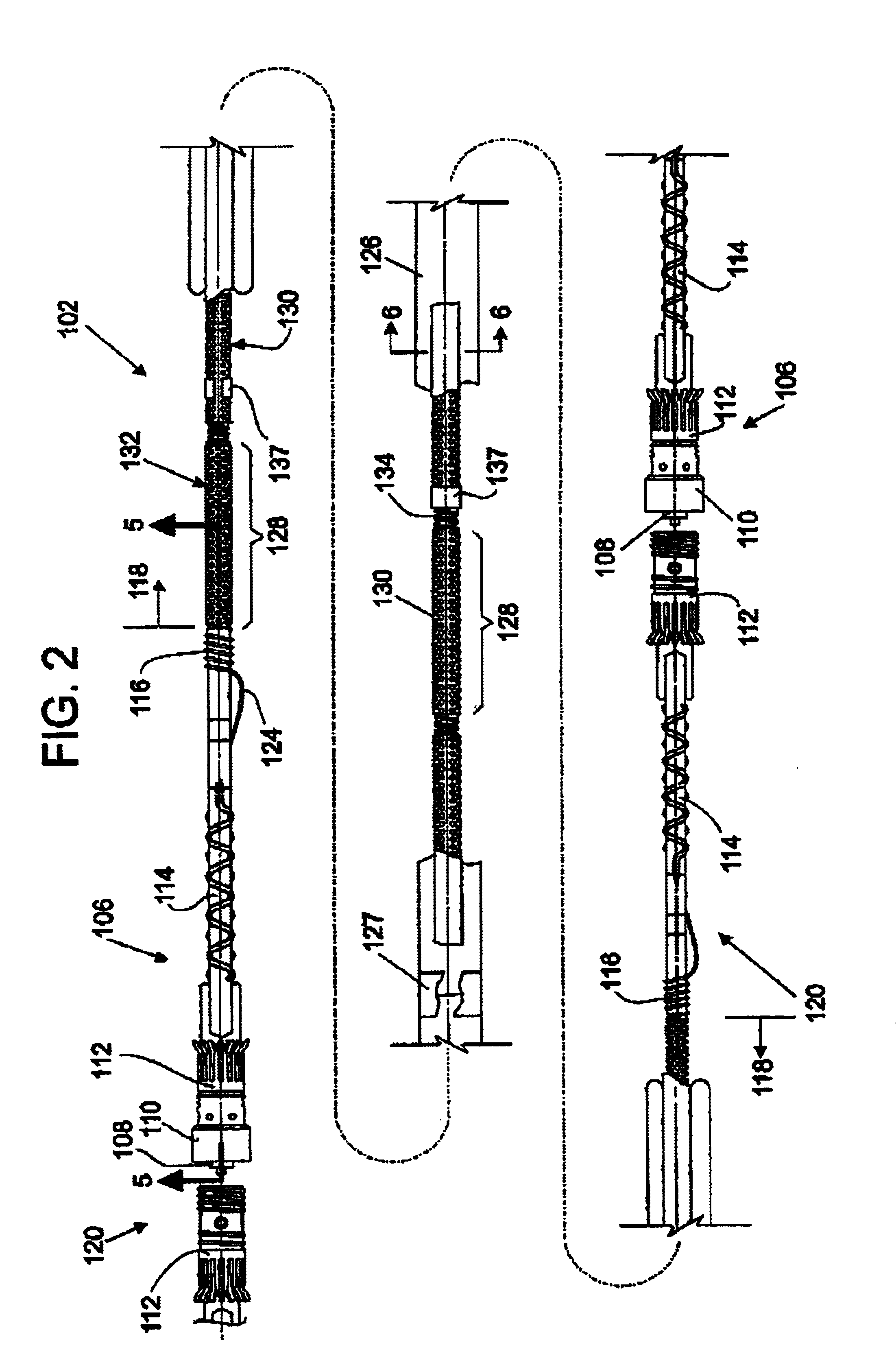
[0061]Referring now to the drawings, wherein like reference numerals illustrate corresponding or similar elements throughout the several views, there is shown in FIG. 1 a submarine 90 using a tow cable 92 to tow an optical hydrophone sonar array 100. The hydrophone array 100 is a linear array of modules 102 connect...


PUM


Abstract

A fiber splice tray for connecting optical fibers between hydrophone modules, allowing each module to be independently assembled. The tray houses the optical fiber in a small space envelope, and allows positioning of a spliced fiber along a straight portion of an internal groove. The internal groove has alternate paths for housing the fiber. The internal groove comprises two opposing parallel sections and two arcs at both ends of the parallel sections, making two continuous looped alternative fiber paths. The internal groove may further comprise two sections that are alternatives to the parallel sections and that cross each other in the middle of the tray. The various alternative fiber paths make it possible to position a splinted optical fiber splice or splice sleeve, which cannot tolerate a bend in the path, in a straight section of the groove.

Description


Claims


Application Information

Patent Timeline
Owner GENERAL DYNAMICS MISSION SYST INC
Learn More