
Engagement set with locking arrangement and rear crossover configuration

a technology of rear crossover and engagement ring, which is applied in the field of wedding bands and engagement rings, can solve the problems of not being particularly attractive, not being worn together, and the degree of balance and visual integration of the two rings of the set, so as to promote comfort and fit in wearing, and positive emotional experien

Inactive Publication Date: 2005-03-22
SAMUEL AARON LICENSING
View PDF46 Cites 3 Cited by
  • Summary
  • Abstract
  • Description
  • Claims
  • Application Information

AI Technical Summary

Benefits of technology

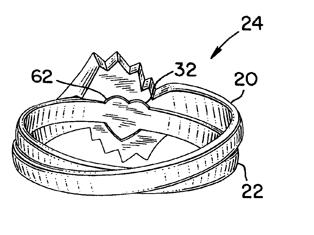
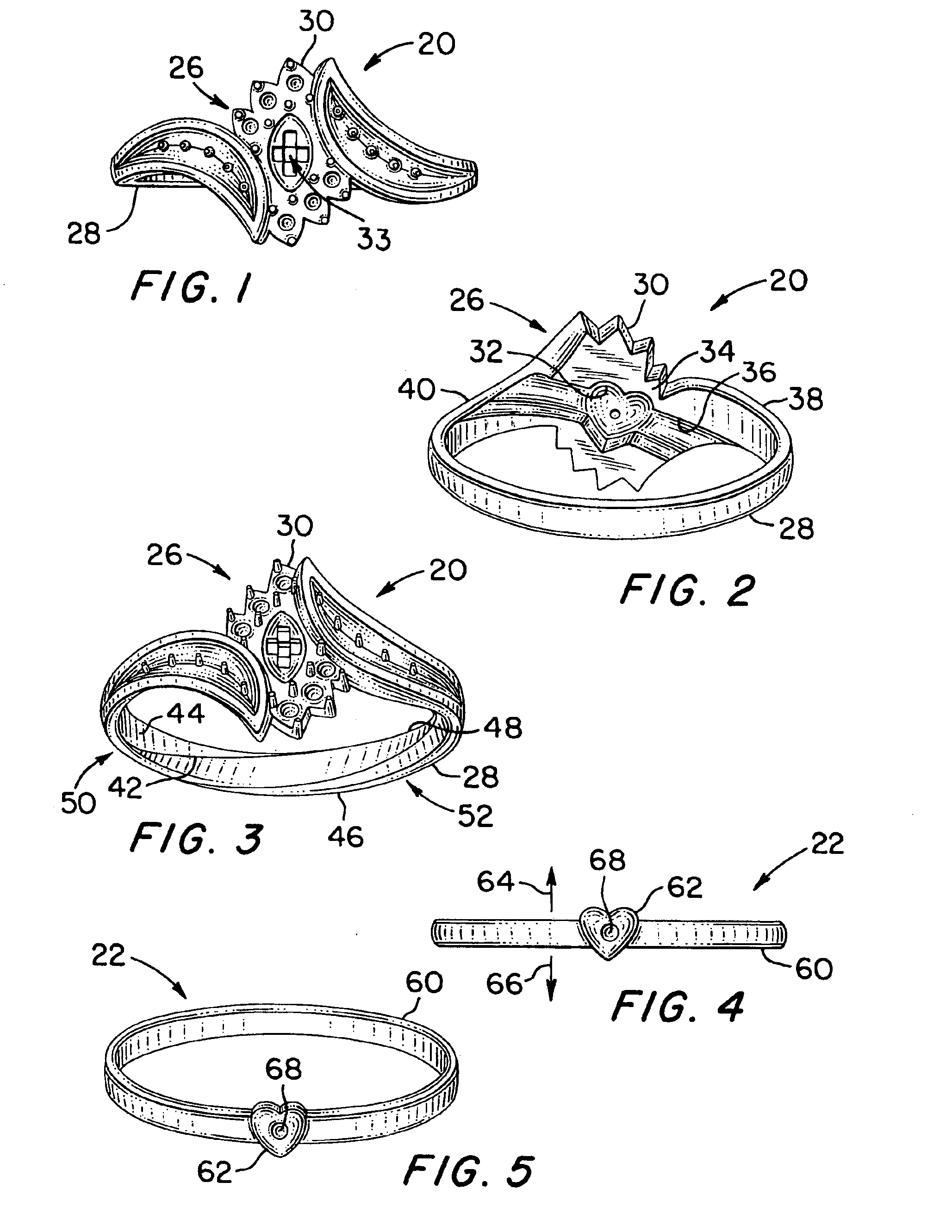
In an engagement set in accordance with one or more aspects of the present invention, the engagement ring and the wedding band may be securely joined together so as to promote comfort fit in wearing the two rings. The two rings may cross at the backs of the rings to form an “X” configuration. Since an “X” is a traditional symbol of a “kiss”, the cross configuration of the ring backs may convey a positive emotional experience to the wearer.
Furthermore, the locking mechanism between the two rings may include a feature and a recess having a heart-shaped or “x” shaped profile, which also may symbolize affection and love, and may also convey a positive emotional experience to the wearer. Also, since the locking mechanism features may be hidden while the rings are worn, the love and affection symbolized by the locking mechanism may be represented as “secret” or private, which may further enhance the positive emotional experience conveyed to the wearer. Even regardless of the specific profile of the locking mechanism components, the locking mechanism itself may symbolize the union between the wearer and her spouse, thereby again conveying a positive emotional experience to the wearer.

Problems solved by technology

However, the degree of balance and visual integration of the two rings of the set, when not worn together, often is not particularly appealing.

Method used


Image

  • Engagement set with locking arrangement and rear crossover configuration
  • Engagement set with locking arrangement and rear crossover configuration
  • Engagement set with locking arrangement and rear crossover configuration

Examples


third embodiment

the invention will now be described with reference to FIGS. 10-16.

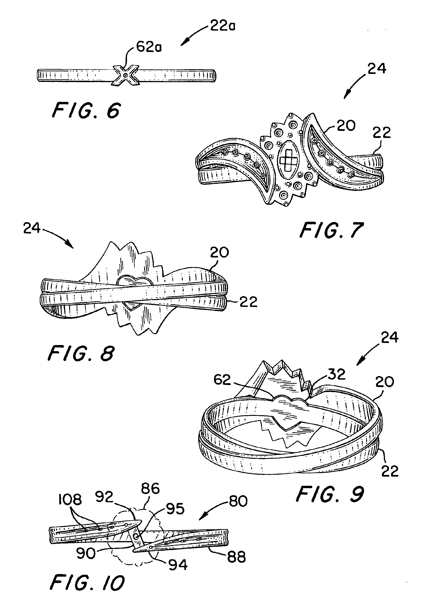
An engagement ring 80 of the engagement set according to the third embodiment is shown by itself in FIGS. 10-12. A wedding band 82 of the engagement set according to the third embodiment is shown by itself in FIGS. 13-14A. The engagement set 84 of the third embodiment, consisting of the engagement ring 80 and the wedding band 82, is shown in FIGS. 15 and 16 with the rings 80 and 82 coupled together.

FIG. 10 is a front view of the engagement ring 80; FIG. 11 is a perspective view of the engagement ring 80 taken from behind the engagement ring; and FIG. 12 is a perspective view of the engagement ring 80 taken from in front of the engagement ring. (In FIGS. 10 and 15 an ornamental setting 86 of the engagement ring 80 is shown in phantom so as to allow certain structural features of the engagement ring to be more clearly depicted; in the other drawings, the ornamental setting is omitted for the same reason.)

The engagement ...


PUM


Abstract

An engagement set includes a wedding band and an engagement ring to which the wedding band is removably coupled. The shank of the wedding band when joined together with the engagement ring may be inclined relative to the shank of the engagement ring to form an “X” configuration and thereby to symbolize a “kiss”. The engagement set may be joined by a locking mechanism formed of a locking feature on the wedding band and a corresponding recess on the inner surface of the front of the engagement ring. The locking feature and the recess may have an emotionally symbolic shape such as a heart shape or an “X”. There may be an inclined groove at an inner surface of the back of the engagement ring to accommodate the shank of the wedding band when the rings are coupled together.

Description

FIELD OF THE INVENTIONThis invention relates to jewelry and more particularly to wedding band-engagement ring sets (also known as “engagement ring sets” or “engagement sets”).BACKGROUND OF THE INVENTIONEngagement sets are well known. However, the degree of balance and visual integration of the two rings of the set, when not worn together, often is not particularly appealing. Moreover, the present inventor has recognized opportunities for novel engagement set configurations that attractively symbolize and express a married couple's mutual love and affection, unity and connection to each other. These novel configurations may also promote secure and comfortable wearing of the two rings of the engagement set.SUMMARY OF THE INVENTIONAccording to a first aspect of the invention a ring set includes a first ring and a second ring. The first ring has a main body configured to encircle or substantially encircle a wearer's finger, and a feature on the main body, the feature having a profile. T...

Claims


Application Information

Patent Timeline
IPC IPC(8): A44C9/00
CPCA44C9/0023
Inventor BAUM, ROBERTLEONI, LAURASINISHTAY, MIRASH
Owner SAMUEL AARON LICENSING
Learn More