
Cup pads having light emitting members

a technology of light-emitting members and cups, which is applied in the field of cups, can solve problems such as attracting people's attention

Inactive Publication Date: 2005-03-08
LU SHANG KUAI
View PDF9 Cites 33 Cited by
  • Summary
  • Abstract
  • Description
  • Claims
  • Application Information

AI Technical Summary

Benefits of technology

In accordance with one aspect of the present invention, there is provided a cup pad which comprises a top part and a bottom part connected to the top part. The first part has a recessed area for receiving a cup and a plurality of first holes are defined through the recessed area and a plurality of second holes are defined through the top part and located around the recessed area. An electric power source is connected to the bottom part so as to provide electric power to a circuit board sandwiched between the top part and the bottom part. A plurality of first light em...

Problems solved by technology

However, whatever the decoration of the conventional pads is made, the pads are hardly attract people's attention because there are similar decorations and colors around the users so that the cup pads cannot play an attractive role and this inherent problem is one of the main concerns for the manufacturers of the cup pads.

Method used


Image

  • Cup pads having light emitting members
  • Cup pads having light emitting members
  • Cup pads having light emitting members

Examples


Embodiment Construction

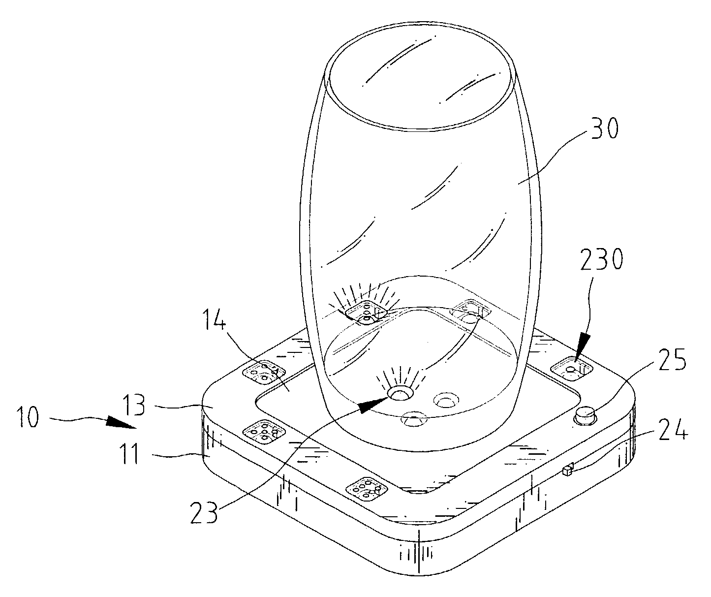
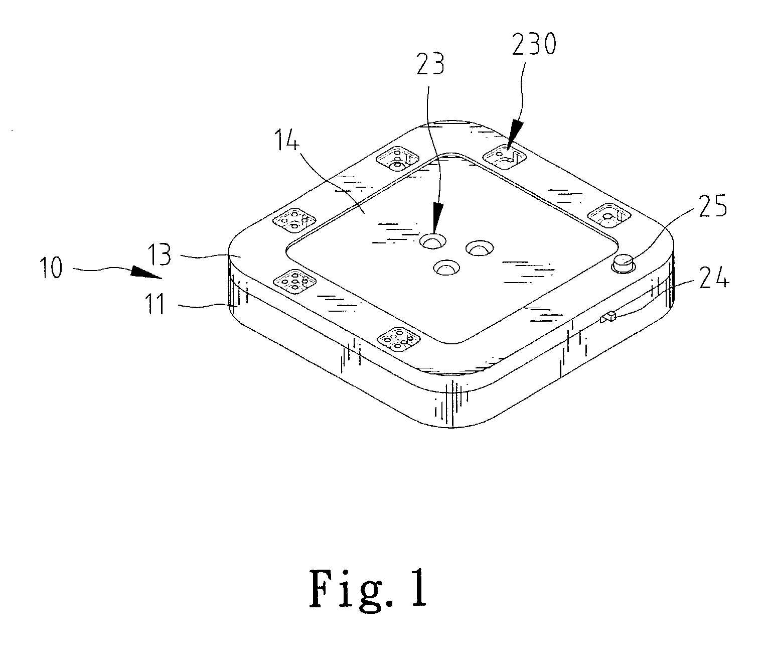
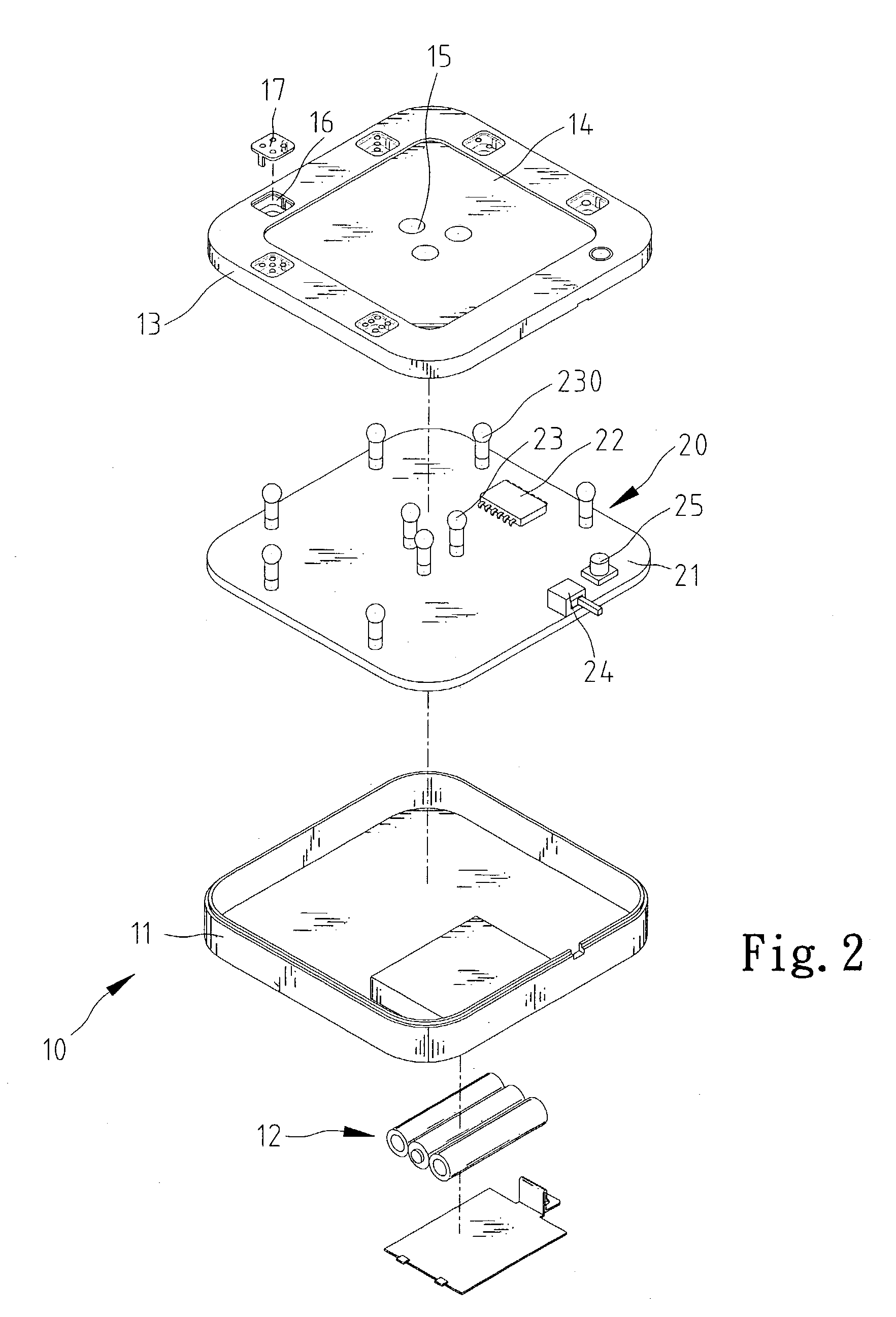
Referring to FIGS. 1 and 2, the cup pad 10 of the present invention comprises a top part 13, a bottom part 1 which is engaged with the top part 13 and a circuit board 20 which is sandwiched between the top part 13 and the bottom part 11. The top part 13 has a recessed area 14 defined in a top thereof so that a cup 30 as shown in FIG. 5 may put in the recessed area 14. A plurality of first holes 15 are defined through the recessed area 14. A plurality of second holes 16 are defined through the top part 13 and located around the recessed area 14. A transparent cover 17 is engaged with each of the second holes 16 and can be decorated to have different number of dots on it.

The bottom part 11 has a space for receiving an electric power source 12 such as batteries therein. The circuit board 20 has a plurality of first light emitting members 23 and second light emitting members 230 thereon, and a control chip 22 is located on the circuit board 20 so as to control the first light emitting...


PUM


Abstract

A cup pad includes a top part having a recessed area for a cup to put therein and a plurality of first holes are defined through the recessed area. A plurality of second holes are defined through the top part and located around the recessed area. A bottom part is engaged with the top part and an electric power source is connected to the bottom part. A circuit board is sandwiched between the top part and the bottom part. A plurality of first light emitting members are inserted in the first holes and second light emitting members are inserted in the second holes. These light emitting members are controlled by a control chip on the circuit board so as to light up in a pre-determined way.

Description

FIELD OF THE INVENTION The present invention relates to a cup pad having first light emitting members on a center of a recessed area thereof and second light emitting members located around the recessed area. BACKGROUND OF THE INVENTION A conventional cup pad is made of plastic or even cord so as to prevent heat from being transferring to the top of the table. Most of the conventional cup pads are decorated with different patterns and colors so as to increase their value. However, whatever the decoration of the conventional pads is made, the pads are hardly attract people's attention because there are similar decorations and colors around the users so that the cup pads cannot play an attractive role and this inherent problem is one of the main concerns for the manufacturers of the cup pads. The present invention intends to provide a cup pad that includes first tight emitting members on a central area of the pad and second light emitting members around the central area, such that the...

Claims


Application Information

Patent Timeline
IPC IPC(8): F21V33/00A47G23/03
CPCA47G23/0309F21V33/0024Y10S362/806F21Y2101/02F21V33/0036F21Y2115/10
Inventor LU, SHANG-KUAI
Owner LU SHANG KUAI
Learn More