
Tool box provided with a seat unit

a seat unit and tool box technology, applied in the field of tool boxes, can solve the problems of the seat unit b>12/b> being moved from the upper position, and the effect of being undesirabl

Inactive Publication Date: 2005-02-22
HSIAO CHIEH JEN
View PDF8 Cites 21 Cited by
  • Summary
  • Abstract
  • Description
  • Claims
  • Application Information

AI Technical Summary

Benefits of technology

Therefore, the object of this invention is to provide a tool box with a seat unit which is capable of overcoming the aforesaid disadvantage of the prior art.

Problems solved by technology

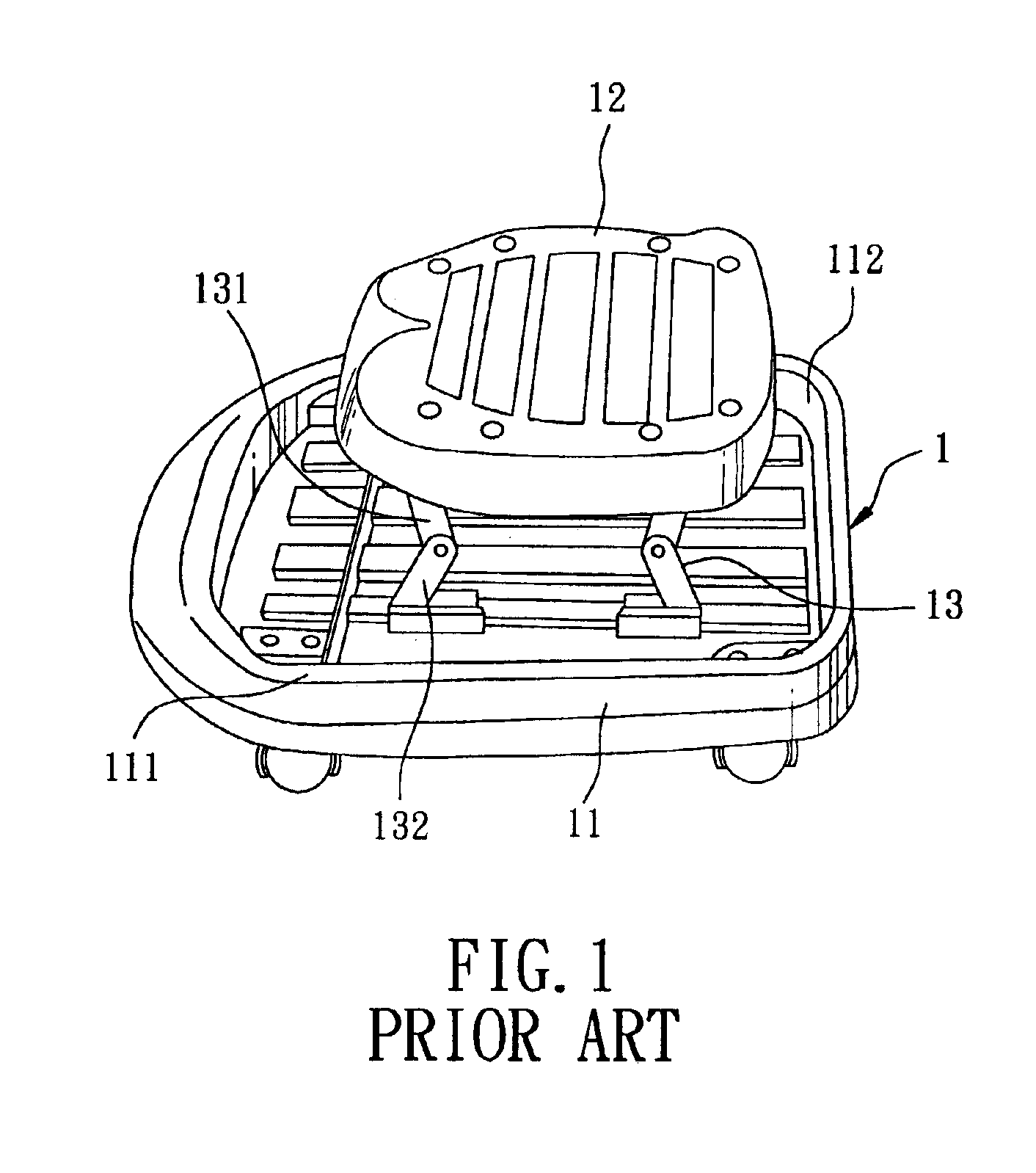
One disadvantage of the conventional tool box resides in that since no fastening device is used for immobilizing the upper and lower links 131,132 when a user sits on the seat unit 12, the seat unit 12 tends to be undesirably and accidentally moved from the upper position to the lower position.

Method used


Image

  • Tool box provided with a seat unit
  • Tool box provided with a seat unit
  • Tool box provided with a seat unit

Examples


Embodiment Construction

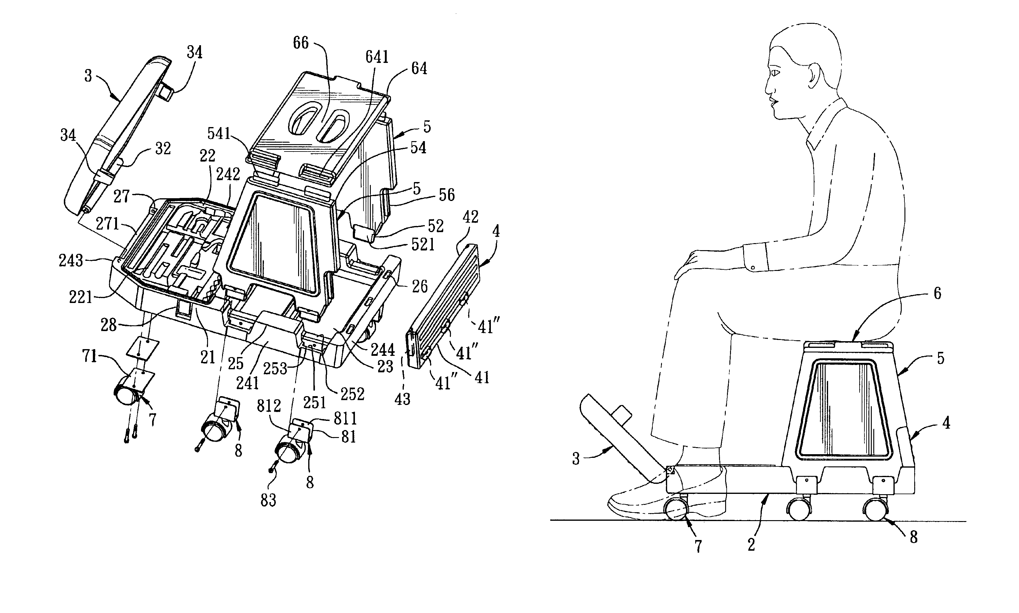
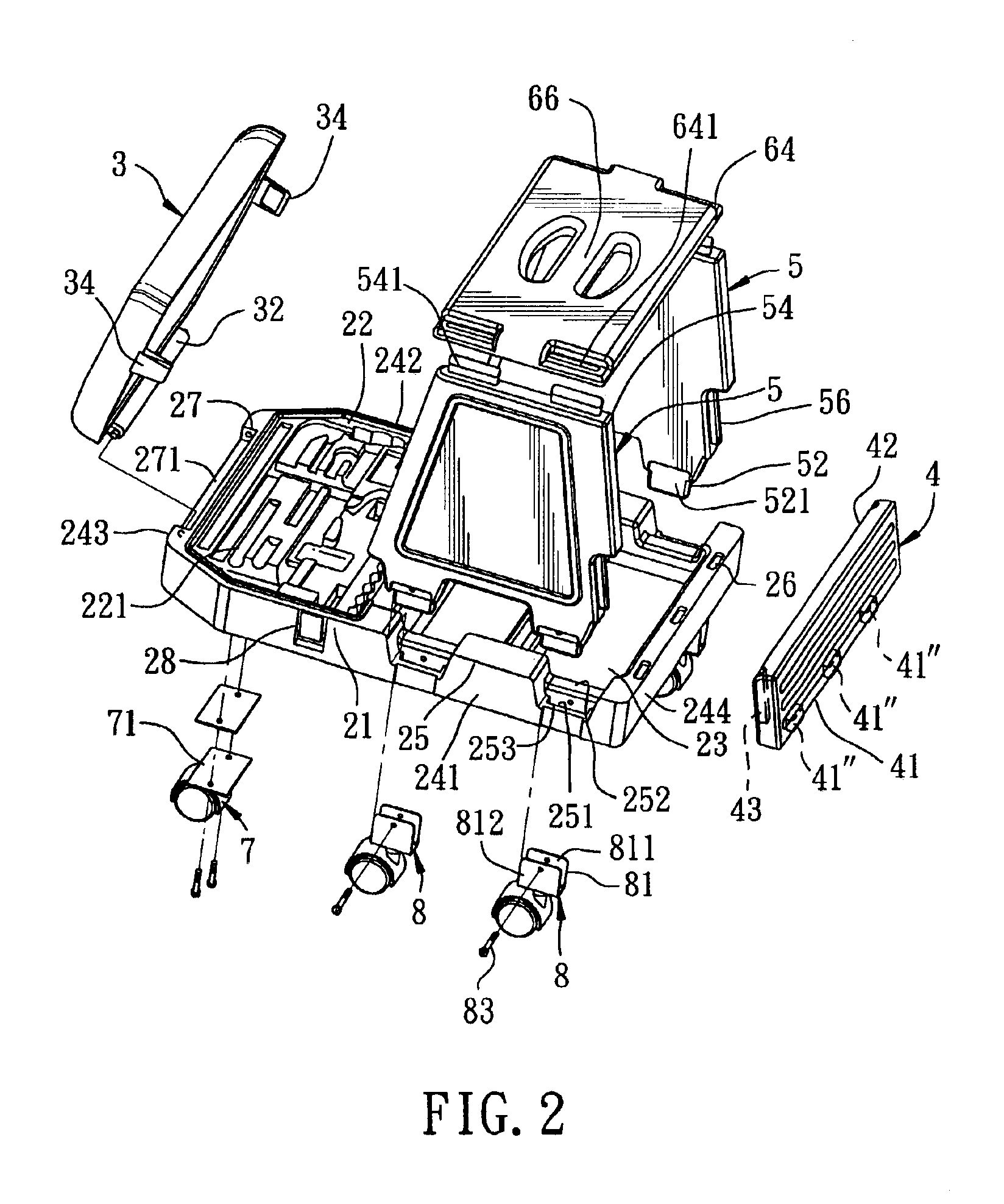
Referring to FIGS. 2 and 3, the preferred embodiment of a tool box according to the present invention is shown to include a base 2, a seat unit 6, a cover member 3, and a caster unit 7,8 that is mounted on a bottom of the base 2 and that includes a plurality of front and rear casters 71,81.

As illustrated, the base 2 is formed from plastic material by a blow-molding process, and includes a front wall 243, a rear wall 244 opposite to the front wall 243, and opposite left and right walls 241,242. Each of the left and right walls 241,242 has a first segment 21 proximate to the front wall 243 and a second segment 25 proximate to the rear wall 244. The first segments 21 of the left and right walls 241,242 cooperate with the front wall 243 to define a tool-receiving space 22 thereamong. The second segment 25 of each of the left and right walls 241,242 is formed with a plurality of lower slots 251.

The seat unit 6 includes left and right support panels 5, a seat panel 66, and a rear support ...


PUM

PropertyMeasurementUnit
stabilityaaaaaaaaaa
areaaaaaaaaaaa

Abstract

A tool box includes a seat unit having left and right support panels mounted on left and right walls of a base. The left and right walls are formed with a plurality of lower slots. The left and right support panels have a plurality of lower inserts which are respectively inserted into the lower slots in the left and right walls, and top ends formed with a plurality of top inserts. A seat panel has two opposite mounting ends, each of which is formed with a plurality of upper slots for receiving the top inserts of the left and right support panels therein.

Description

CROSS REFERENCE TO RELATED APPLICATIONThis application claims priority of Taiwanese Application No. 092201412, filed on Jan. 24, 2003.BACKGROUND OF THE INVENTION1. Field of the InventionThe present invention relates to a tool box, more particularly to a tool box with a seat unit.2. Description of the Related ArtReferring to FIG. 1, a conventional tool box 1 includes a base 11 and a seat unit 12.As illustrated, the base 11 includes a peripheral wall 111 defining a tool-receiving space 112 therein. The seat unit 12 is mounted on the base 11 through a support unit 13 that is foldable and that includes left and right lower links 132 mounted pivotally on the base 11, and left and right upper links 131 that are pivotally connected to the seat unit 12 and the lower links 132 so as to permit adjustment of the seat unit 12 between upper and lower positions.One disadvantage of the conventional tool box resides in that since no fastening device is used for immobilizing the upper and lower link...

Claims


Application Information

Patent Timeline
Patent Type & Authority Patents(United States)
IPC IPC(8): B25H3/00B25H3/02B62B5/00B62B5/08
CPCB25H3/02B62B5/085B62B2501/065B62B2301/08
Inventor HSIAO, CHIEH-JEN
Owner HSIAO CHIEH JEN
Learn More