
All weather precision guidance of distributed projectiles

Inactive Publication Date: 2003-11-25
RAYTHEON CO
View PDF9 Cites 34 Cited by
  • Summary
  • Abstract
  • Description
  • Claims
  • Application Information

AI Technical Summary

Problems solved by technology

Navy ships are exposed to low flying, fast, and highly maneuverable missile threats.
Prior art guidance systems do not work well with smaller caliber projectiles.
In particular, prior art approaches do not accurately measure the line-of-sight angular rate to the target with enough precision for the application.
However, these measurements are generally not as accurate as measurements made from the projectile, as with homing guidance systems.
Poor line-of-sight angular rate measurements may cause a projectile targeting error.
These systems offer very high angular resolution; however, they typically require favorable weather conditions to be effective.
Adverse weather such as fog, rain, or clouds may block optical electromagnetic energy, causing a laser based guidance system to fail.

Method used


Image

  • All weather precision guidance of distributed projectiles
  • All weather precision guidance of distributed projectiles
  • All weather precision guidance of distributed projectiles

Examples


Embodiment Construction

Illustrative embodiments and exemplary applications will now be described with reference to the accompanying drawings to disclose the advantageous teachings of the present invention.

While the present invention is described herein with reference to illustrative embodiments for particular applications, it should be understood that the invention is not limited thereto. Those having ordinary skill in the art and access to the teachings provided herein will recognize additional modifications, applications, and embodiments within the scope thereof and additional fields in which the present invention would be of significant utility.

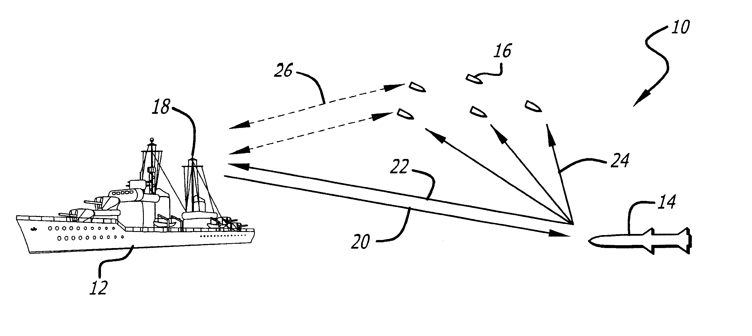
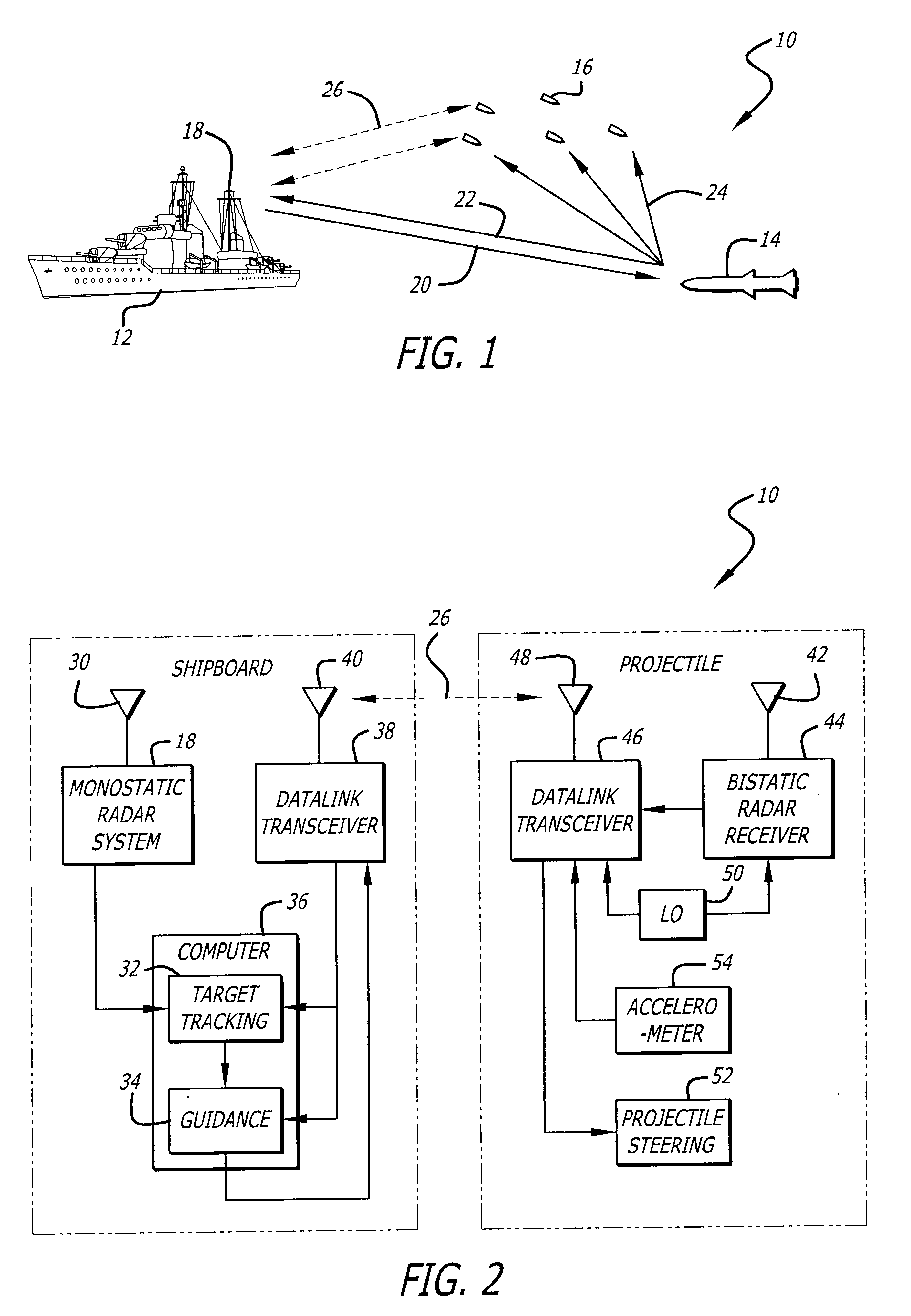
FIG. 1 is a diagram of an anti-ship missile defense system 10 designed in accordance with the present teachings showing a ship 12 and an incoming missile 14, also referred to as the target. The ship 12 fires several projectiles 16 to intercept the missile target 14. A shipboard radar 18 transmits a radar beam 20 towards the target 14. The monostatic reflected re...


PUM


Abstract

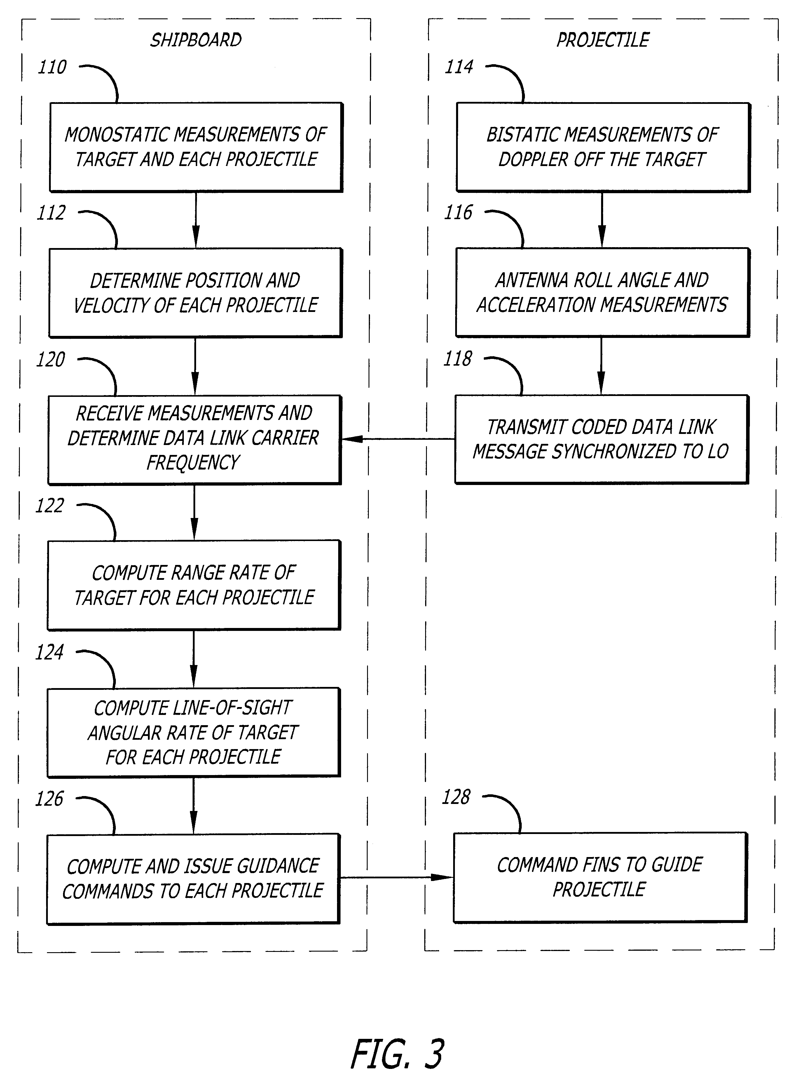
A system and method (32) for measuring line-of-sight angular rates for all-weather precision guidance of distributed projectiles (16) and a guidance system (10) based thereon. In accordance with the novel method (32) for measuring line-of-sight angular rates, first the range rates of the target (14) relative to at least two projectiles (16) is determined, as well as the position and velocity of each projectile (16). Then, the line-of-sight angular rate of the target (14) relative to at least one projectile (16) is computed from the range rates, positions, and velocities. In the illustrative embodiment, the range rate of the target (14) relative to a projectile (16) is determined based on a monostatic target Doppler measurement, a monostatic projectile Doppler measurement, a bistatic Doppler measurement of the target (14) by the projectile (16), and the carrier frequency of a data link (26) between the projectile and the shipboard system. The guidance system (10) of the present invention includes a monostatic radar (18) illuminating the target (14), bistatic receivers (44) aboard at least two projectiles (16) fired at the target (14), and a system (32) for determining line-of-sight angular rates to the target based on the monostatic measurements and the bistatic measurements from at least two projectiles. The guidance system (10) further includes a system (34) for computing guidance command signals for at least one projectile based on the line-of-sight angular rates, and a projectile steering unit (52) aboard at least one projectile for steering the projectile based on the guidance command signals.

Description

1. Field of the InventionThe present invention relates to radar guidance systems. More specifically, the present invention relates to systems and methods for measuring line-of-sight angular rates for guided projectiles.2. Description of the Related ArtNavy ships are exposed to low flying, fast, and highly maneuverable missile threats. In order to provide the ships with an effective missile defense system, high accuracy measurements of incoming missile targets and precision guidance of anti-missile projectiles are required.Many guidance systems have been developed for missiles and projectiles (i.e. --bullets). In a typical radar based guidance system, the projectile is guided to the target by guidance signals developed from tracking data obtained either by a shipboard radar system or by a radar system located totally, or partially, within the projectile. The former system is commonly referred to as a command guidance system and the latter as a homing guidance system.In a command guid...

Claims


Application Information

Patent Timeline
IPC IPC(8): F41G7/20F41G7/30G01S13/72G01S13/00
CPCF41G7/303F41G7/305G01S13/723F41G7/308G01S13/003
Inventor KRIKORIAN, KAPRIEL V.ROSEN, ROBERT A.
Owner RAYTHEON CO
Learn More