
Finish carpentry nailing guard

a carpentry and nailing guard technology, applied in the field of carpentry tools, can solve the problems of mishits by accomplished and unskilled carpenters, fingers injured by mishits, damaged valued surfaces,

Inactive Publication Date: 2003-02-18
GILDROY GRANT
View PDF13 Cites 16 Cited by
  • Summary
  • Abstract
  • Description
  • Claims
  • Application Information

AI Technical Summary

Problems solved by technology

Since the invention of hammers and nails, accomplished and unskilled carpenters alike have injured fingers and damaged valued surfaces with mishits while driving nails.

Method used


Image

  • Finish carpentry nailing guard
  • Finish carpentry nailing guard
  • Finish carpentry nailing guard

Examples


Embodiment Construction

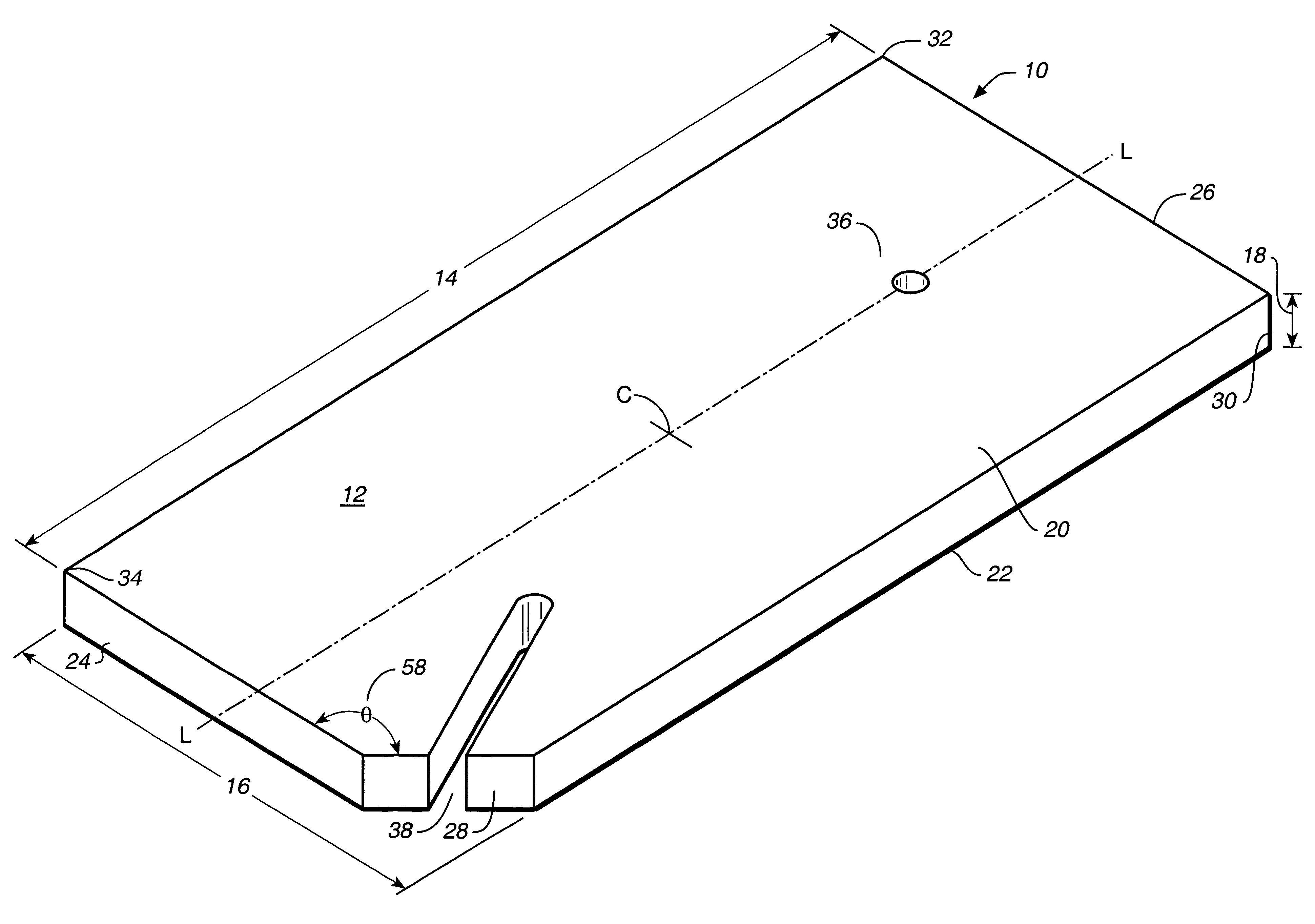
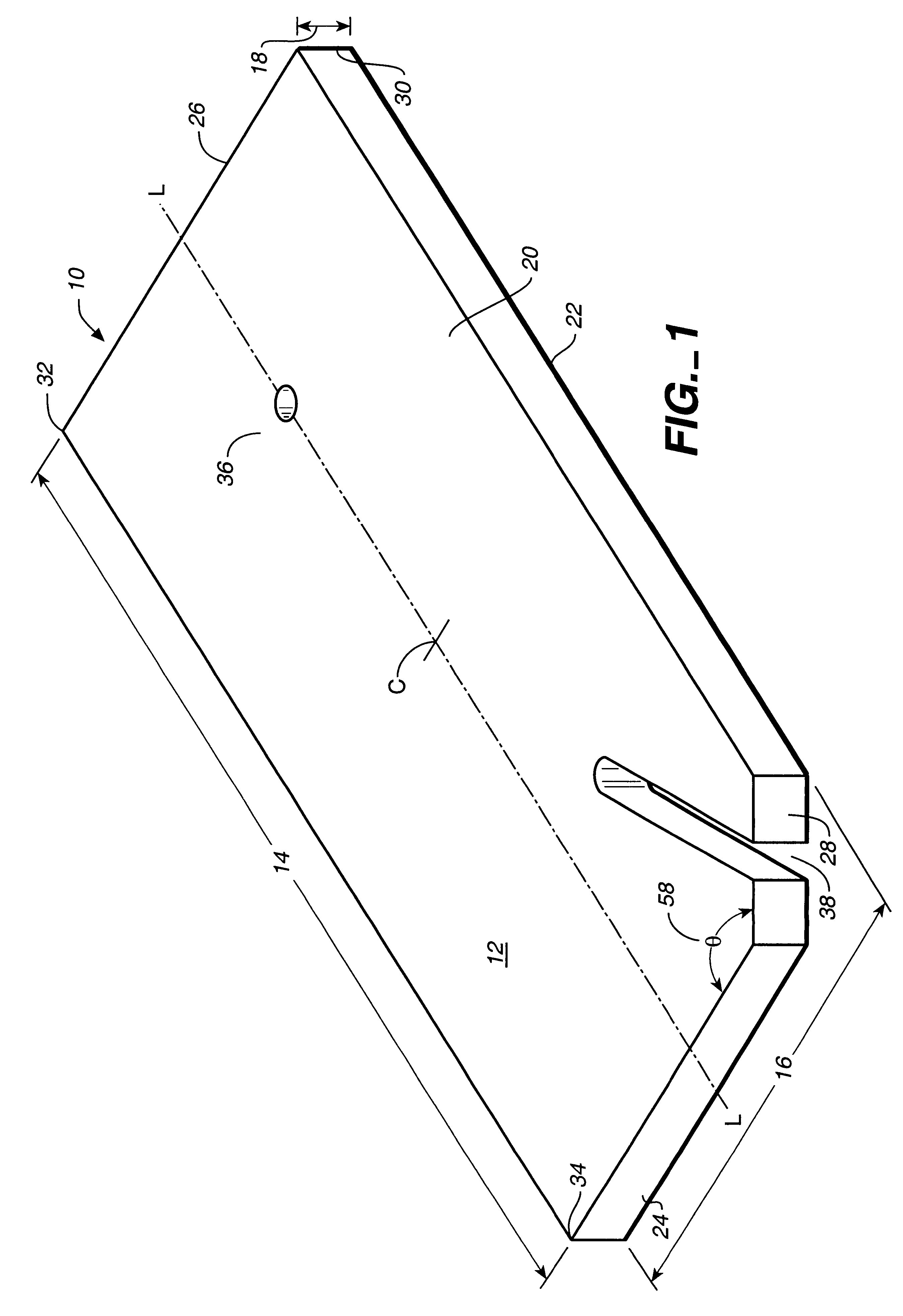
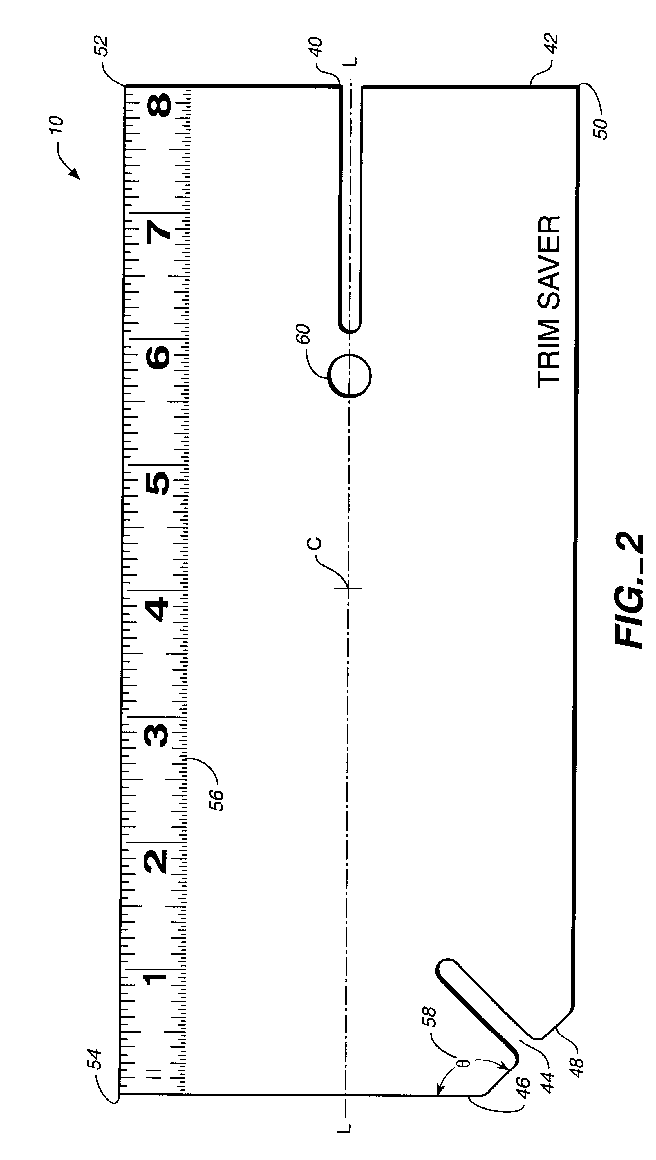
The first preferred embodiment of the present invention, shown in perspective view in FIG. 1 and generally denominated 10, is a finish carpentry nailing guard adapted for use in protecting surfaces from damage by hammers while driving nails and / or from nail pulling devices when removing nails. In this first preferred embodiment, the nail guard comprises a unitary cuboid block 12 having a length 14, a width 16, a depth 18, a top side 20, a bottom side 22, a longitudinal axis L, a center C, a first end 24, a second end 26, a first corner 28, a it second corner 30, a third corner 32, a fourth corner 34, at least one small aperture 36 passing through the block from the top to the bottom side and located along the longitudinal axis slightly closer to one of said first or second ends, and a slot 38, located at the first corner and running at an approximate 45 degree angle relative to the first side 24, and running inwardly toward the longitudinal axis. Preferably the guard is transparent ...


PUM


Abstract

A finish carpentry nailing guard adapted for use in protecting workpiece surfaces from damage by hammers while driving nails and / or from nail pulling devices when removing nails, the guard comprising a unitary block having a centrally located aperture and / or slots. In its preferred embodiment the guard is transparent and fabricated from lexan or other hard plastic.

Description

1. Field of the InventionThe present invention relates generally to carpentry tools, and more particularly to a finish carpentry nailing guard used to prevent damage to the surface worked upon when driving or pulling nails.2. Description of the Prior ArtSince the invention of hammers and nails, accomplished and unskilled carpenters alike have injured fingers and damaged valued surfaces with mishits while driving nails. Accordingly, the prior art includes several devices adapted for use as nail starters, nail holders, and / or nailing shields. However, the present invention improves on the prior art in providing a simpler and more effective guard against damaging a workpiece, particularly one with valuable finish surfaces, when either driving or pulling nails.The present invention is a finish carpentry nailing guard adapted for use in protecting workpiece surfaces from damage by hammers while driving nails and / or from nail pulling devices when removing nails. In its simplest embodiment...

Claims


Application Information

Patent Timeline
IPC IPC(8): B25C3/00
CPCB25C3/008
Inventor GILDROY, GRANT
Owner GILDROY GRANT
Learn More