Livestock chute

a livestock and chute technology, applied in the field of livestock chutes, can solve the problems of difficult access to the sides of the animal, serious injuries, bruises of animals so handled, etc., and achieve the effect of efficient operation

Inactive Publication Date: 2003-02-04
LINN GENE H
View PDF12 Cites 14 Cited by
  • Summary
  • Abstract
  • Description
  • Claims
  • Application Information

AI Technical Summary

Benefits of technology

The present invention provides a livestock chute for confining and controlling an animal for the various treatments thereof. The chute of the present invention provides a more gentle way of handling livestock and may be efficiently operated by one person.
Thus the livestock chute of the present invention has several unique features which allows the confining and controlling of an animal for various treatment by ranchers, farmers and veterinarians in a much safer, gentler, less traumatic and less stressful manner. Furthermore, it allows access to the entire animal for such treatments. It may be efficiently operated by one person. Many other objects and advantages of the invention will be apparent from reading the description which follow in conjunction with the accompanying drawings.

Problems solved by technology

However, animals driven into a livestock chute do not normally want to move forward and place their heads in a head gate, even when confined in the chute.
Animals so handled are often bruised and may even be seriously injured in this somewhat harsh and violent procedure.
This requires movement of heavy and lengthy panels and in some cases does not provide easy access to sides of the animal.
Although a number of livestock chutes are commercially available, most of them do not allow one man operation or the flexibility of the various treatments required in ranching and veterinary procedures.
Furthermore, many of them result in harsh treatment of an animal, particularly in driving the animal forward in the chute for locking its head in a head gate.

Method used


Image

  • Livestock chute
  • Livestock chute
  • Livestock chute

Examples


Embodiment Construction

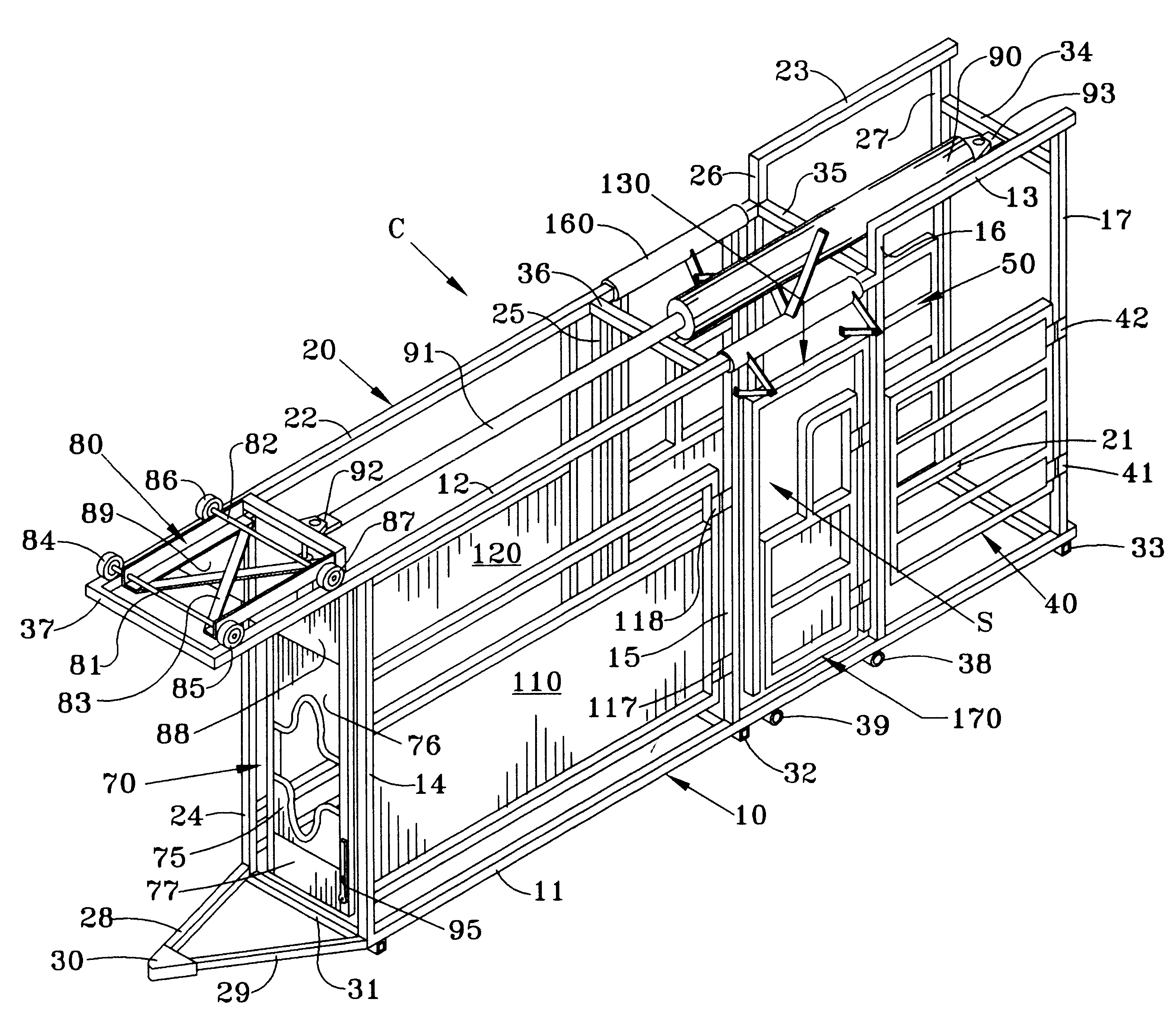
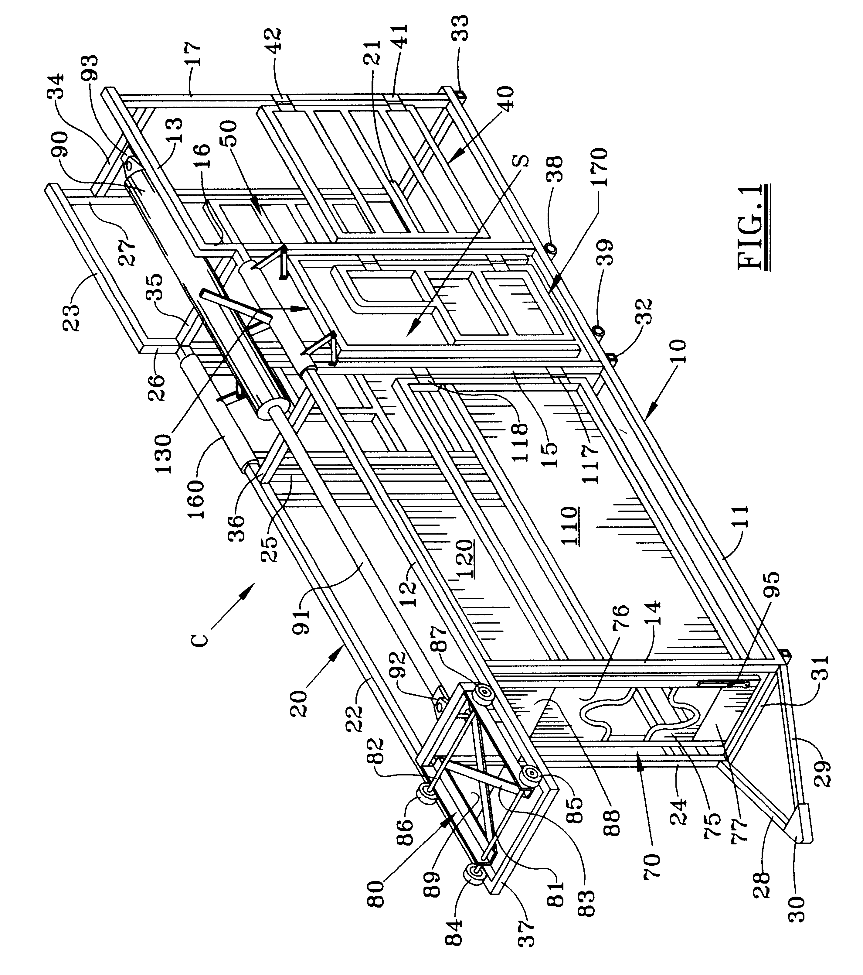
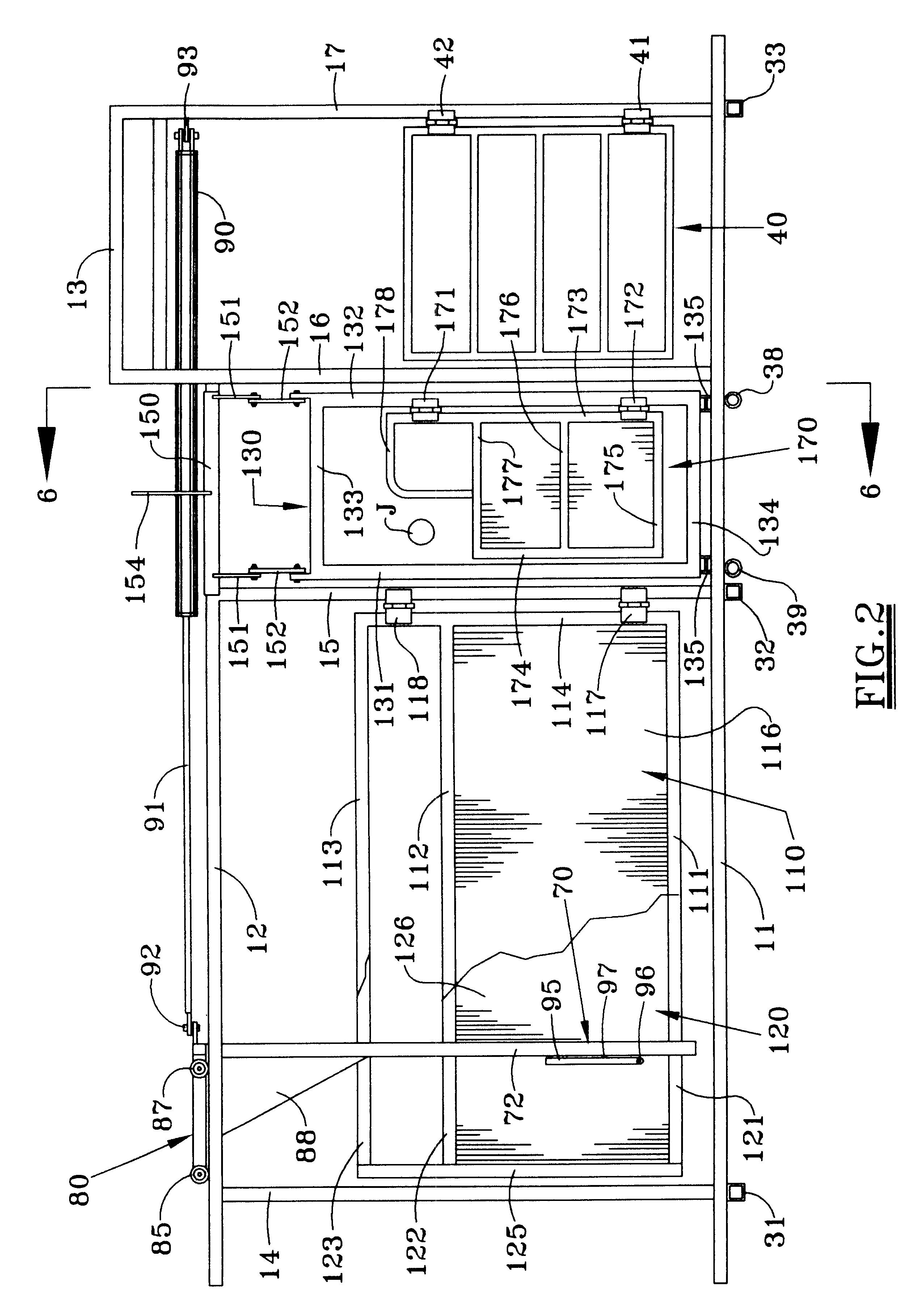
Referring first to FIGS. 1 and 2, there is shown a livestock chute C for confining and controlling animals, typically cattle, for various treatments thereof, e.g. medical treatments, branding, dehorning, palpation, surgery, etc. The chute may be described as having a pair of side frames 10 and 20 spaced apart from each other to provide an elongated space into which an animal may be driven. Each of the side frames may be defined by horizontal structural members 11, 12, 13 for one side, 21, 22, 23 for the other side and vertical structural members 14, 15, 16, 17 for one side and 24, 25, 26, 27 for the other side. The structural members of each of the side frames 10 and 20 may be connected by structural cross supports 31, 32, 33, 34, 35, 36, 37, etc. The structural members may be conveniently formed from square (or round) steel tubing welded together as shown.

If desired, structural members 28 and 29, forming a triangle with structural member 31, may be attached to the side frames 10, 2...


PUM


Abstract

A livestock chute for confining and controlling an animal including a pair of spaced apart side frames connected by support members to provide an elongated space into which the animal may be driven, a tailgate near the rear end of said space and a head gate assembly supported near a front end of the space which includes an expandable and contractible opening which, when expanded, allows the head of the animal to extend therethrough and, when contracted, surrounds the neck of the animal to prevent removal of said animal's head therefrom. A gate carriage is mounted near the top of the side frame for longitudinal movement relative thereto and from which the head gate assembly is suspended for movement between a terminal position near the front of the space and selected positions nearer the rear of said space. Preferred embodiments include a squeeze assembly for engagement with the hip area of the animal.

Description

1. Field of the InventionThe present invention pertains to livestock chutes. More specifically, the present invention pertains to chutes primarily for confining and controlling cattle for various treatments thereof, e.g. examination, medical treatment, branding, palpation, surgery, etc.2. Description of the Prior ArtLivestock chutes for confining and controlling animals, specifically cattle, have been in use for many years. A typical chute is long and narrow providing an elongated space into which one animal at a time may be driven. The chute is usually provided with an entry or tailgate which is opened as the animal is driven into the chute. Once the animal is driven into the chute, the tailgate is closed preventing the animal from backing out of the space.Typically, the chute is provided, near the front end of the elongated space, with a "head gate". There are basically three head gate designs, commonly referred to as: (1) saloon door; (2) guillotine and (3) scissor types. The pur...

Claims


Application Information

Patent Timeline
Patent Type & Authority Patents(United States)
IPC IPC(8): A01K1/06A01K1/00
CPCA01K1/0613
Inventor LINN, GENE H.
Owner LINN GENE H
Why Eureka
Try Eureka