
Dynamic virtual articulator for simulating occlusion of teeth

a virtual articulator and occlusion technology, applied in the field of virtual articulators, can solve the problems of insignificant functionality or visual aesthetics, no possibility to perform a concurrent modeling of restorations, and the motion surface of the restoration may penetrate the unmodified tooth, and achieve the effect of providing a distance between the teeth

Active Publication Date: 2019-09-26
3SHAPE AS
View PDF0 Cites 23 Cited by
  • Summary
  • Abstract
  • Description
  • Claims
  • Application Information

AI Technical Summary

Benefits of technology

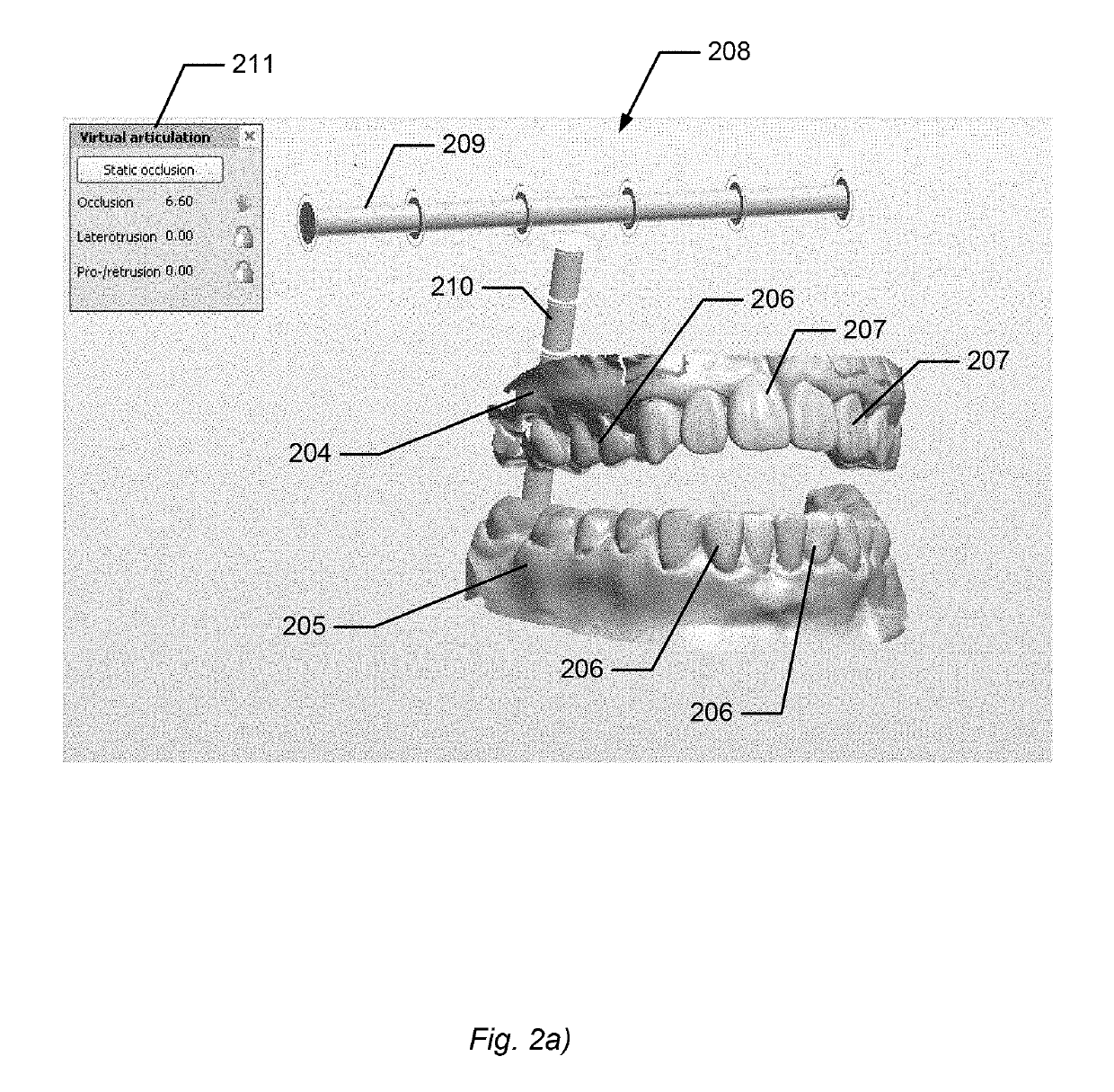
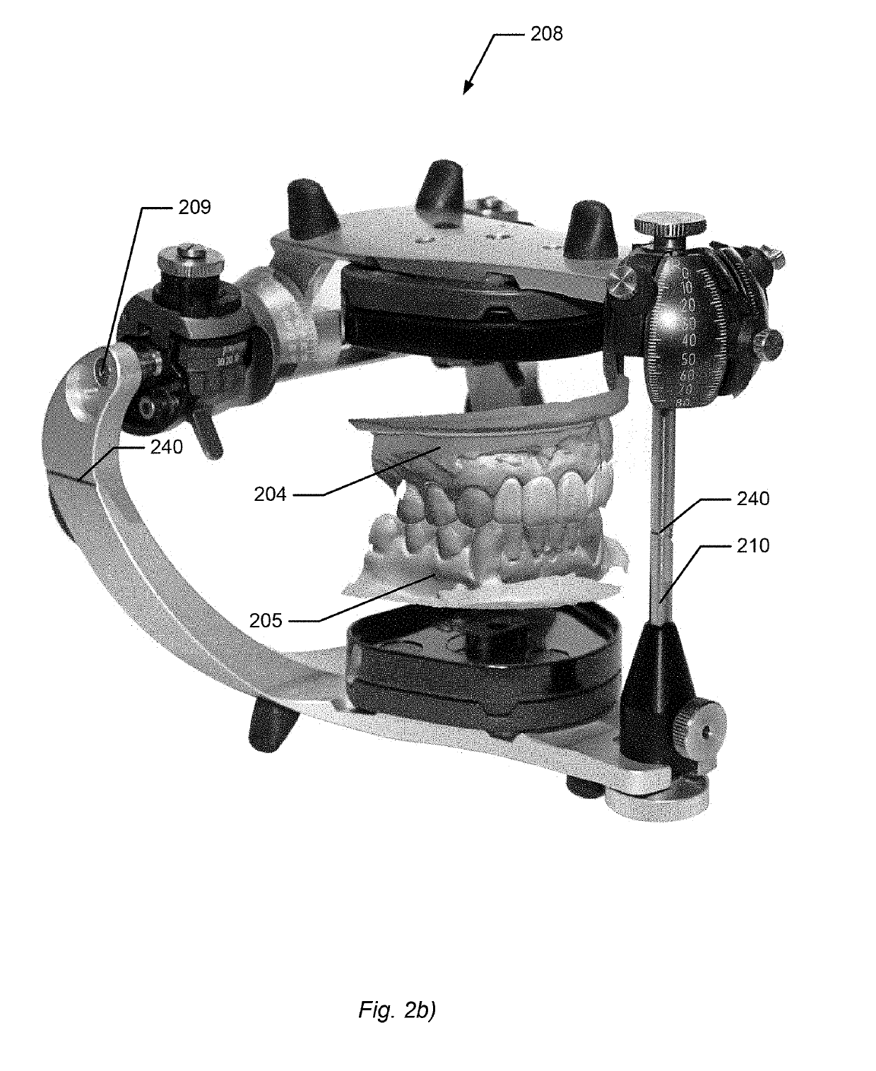
The virtual articulator is a tool that helps dental professionals design dental restorations like crowns or bridges. It allows them to check if the restorations are the right size and shape, and if there is enough space in the mouth for them when the jaws move. This helps ensure that the dental restorations function correctly. The tool uses parameters and contact criteria to improve the occlusion, making it more aligned with the patient's natural dental occlusion.

Problems solved by technology

It remains a problem to provide a virtual articulator which imitates and resembles an articulator in an improved manner.
However, it may alternatively be the case that when a restoration and an unmodified tooth are simulated relative to each other, the motion surface of the restoration may penetrate the unmodified tooth.
Thus no movement, no accumulated registration of collision point surfaces and no possibility to perform a concurrent modeling of restorations based on all collision points are disclosed or possible in prior art.
Whereas other teeth have no important function or position, and it may therefore be insignificant for the functionality or visual aesthetics if those teeth are moved.
It is a problem if a restoration becomes too high, such as extending a little above the neighbor teeth, because then it may interrupt the patient's bite and / or easily become broken.

Method used


Image

  • Dynamic virtual articulator for simulating occlusion of teeth
  • Dynamic virtual articulator for simulating occlusion of teeth
  • Dynamic virtual articulator for simulating occlusion of teeth

Examples


Embodiment Construction

[0382]In the following description, reference is made to the accompanying figures, which show by way of illustration how the invention may be practiced.

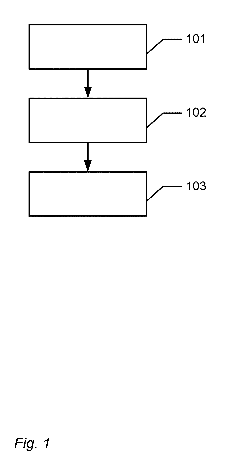
[0383]FIG. 1 shows an example of a flow chart showing the steps of the computer-implemented method of using a dynamic virtual articulator for simulating occlusion of teeth, when performing computer-aided design of one or more dental restorations for a patient.

[0384]In step 101 the virtual articulator comprising a virtual three-dimensional model of the upper jaw and a virtual three-dimensional model of the lower jaw resembling the upper jaw and lower jaw, respectively, of the patient's mouth is provided.

[0385]In step 102 movement of the virtual upper jaw and the virtual lower jaw relative to each other is provided for simulating dynamic occlusion, whereby collisions between teeth in the virtual upper and virtual lower jaw occur;

[0386]In step 103 the teeth in the virtual upper jaw and virtual lower jaw are provided to be blocked from p...


PUM


Abstract

Disclosed is a computer-implemented method of using a dynamic virtual articulator for simulating occlusion of teeth, when performing computer-aided designing of one or more dental restorations for a patient, where the method includes the steps of: providing the virtual articulator including a virtual three-dimensional model of the upper jaw and a virtual three-dimensional model of the lower jaw resembling the upper jaw and lower jaw, respectively, of the patient's mouth; providing movement of the virtual upper jaw and the virtual lower jaw relative to each other for simulating dynamic occlusion, whereby collisions between teeth in the virtual upper and virtual lower jaw occur; wherein the method further includes: providing that the teeth in the virtual upper jaw and virtual lower jaw are blocked from penetrating each other's virtual surfaces in the collisions.

Description

CROSS REFERENCE TO RELATED APPLICATIONS[0001]The present application is a continuation of U.S. application Ser. No. 13 / 580,876, filed on Nov. 29, 2012, which is a U.S. national stage of International Application No. PCT / DK2011 / 050047, filed on Feb. 17, 2011, which claims the benefit of: U.S. Provisional Application No. 61 / 383,840, filed on Sep. 17, 2010; U.S. Provisional Application No. 61 / 334,681, filed on May 14, 2010; and U.S. Provisional Application No. 61 / 307,934, filed on Feb. 25, 2010, and claims the benefit of: Danish Application No. PA 2010 00835, filed on Sep. 17, 2010; Danish Application No. PA 2010 00425, filed on May 14, 2010; and Danish Application No. PA 2010 00156, filed on Feb. 25, 2010. The entire contents of U.S. application Ser. No. 13 / 580,876, International Application No. PCT / DK2011 / 050047 and U.S. Provisional Application Nos. 61 / 383,840, 61 / 334,681, 61 / 307,934, Danish Application No. PA 2010 00835, Danish Application No. PA 2010 00425, and Danish Application N...

Claims


Application Information

Patent Timeline
IPC IPC(8): A61C11/00A61C13/00A61C19/05
CPCA61C9/0086A61C19/045A61C11/00A61C19/05G16H20/40A61C13/0004A61C9/0053A61C13/097G16H50/50
Inventor FISKER, RUNEBARTHE, CHRISTOPHE VASILJEVKRISTENSEN, KASPER KABELPOULSEN, TOMMY SANDDAL
Owner 3SHAPE AS
Learn More