Menstrual fluid collection device and method thereof

a menstrual fluid collection and menstrual cup technology, applied in the field of menstrual cups, can solve the problems of many women using many women's typical menstrual cups, which are often too large to comfortably fit and use them

Active Publication Date: 2019-05-02
HU KATE
View PDF3 Cites 14 Cited by
  • Summary
  • Abstract
  • Description
  • Claims
  • Application Information

AI Technical Summary

Problems solved by technology

That is, typical menstrual cups are often too large to comfortably fit and be used by many women.

Method used


Image

  • Menstrual fluid collection device and method thereof
  • Menstrual fluid collection device and method thereof
  • Menstrual fluid collection device and method thereof

Examples


Embodiment Construction

[0034]Reference will now be made in detail to the exemplary embodiments of the present general inventive concept, examples of which are illustrated in the accompanying drawings, wherein like reference numerals refer to the like elements throughout. The exemplary embodiments are described below in order to explain the present general inventive concept by referring to the figures.

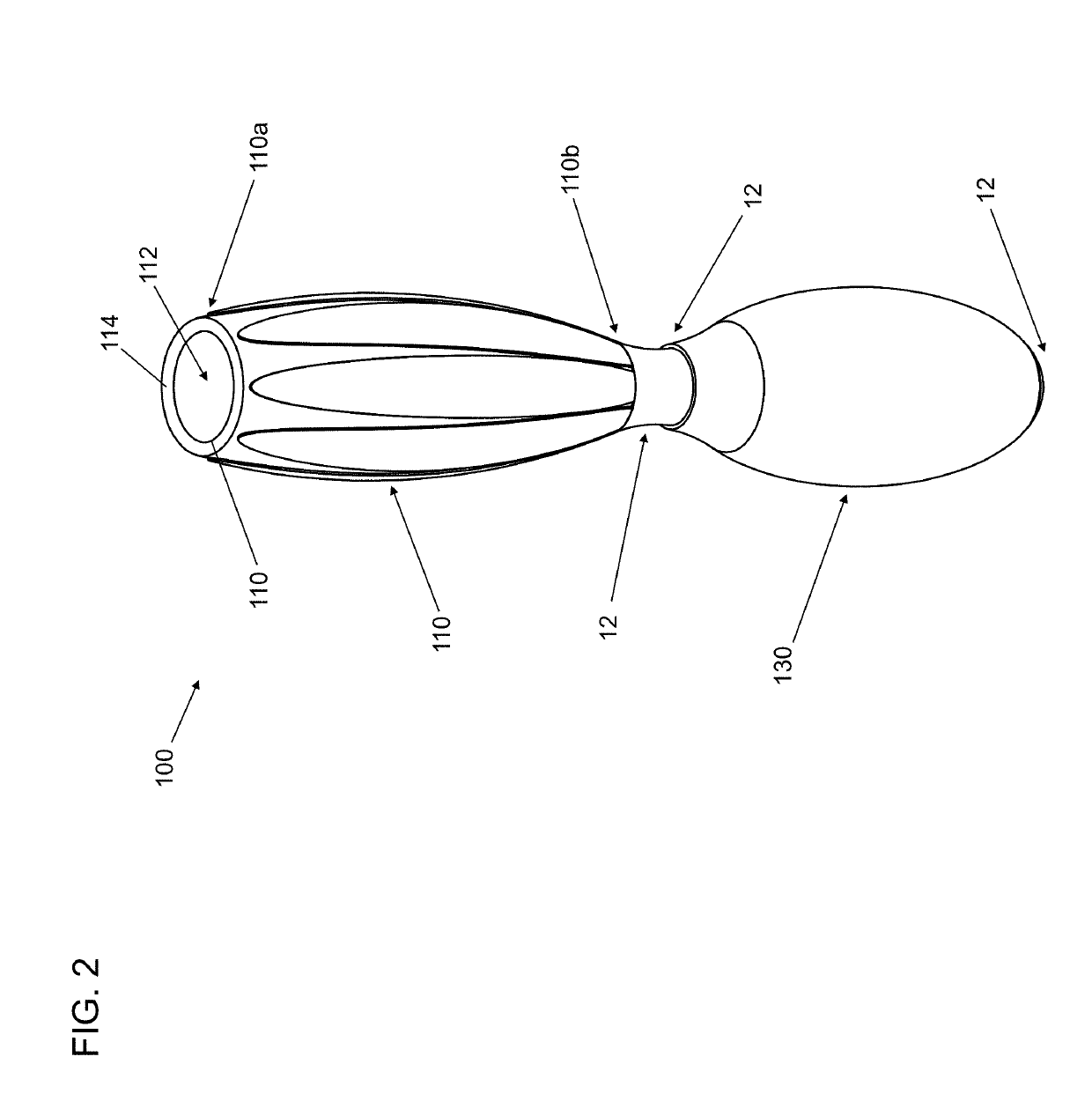
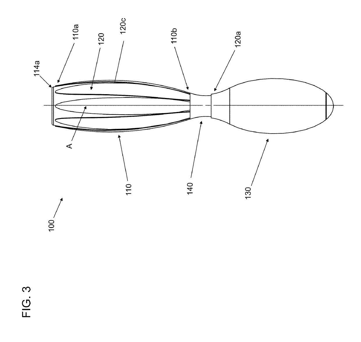
[0035]FIG. 2 is a front perspective view of a menstrual fluid collection device 100 according to an exemplary embodiment of the present general inventive concept, in a closed position 114a. FIG. 3 is a front view of the menstrual fluid collection device 100 illustrated in FIG. 2, a closed position 114a. FIG. 4 is a cross-sectional view of the menstrual fluid collection device 100 illustrated in FIG. 3, along line A and FIG. 5 is a front view of the menstrual fluid collection device 100 illustrated in FIG. 2, in an open position 114b. FIG. 6 is a cross-sectional view of the menstrual fluid collection device 10...


PUM


Abstract

A menstrual fluid collection device including a flexible container having a storage cavity to store a fluid and a movable opening formed in a closed position at a first end of the flexible container, the storage cavity to receive the fluid when the movable opening is in an open position and an inflatable seal member coupled to and extending around the flexible container, the inflatable seal member configured to move the opening to the open position, when inflated.

Description

FIELD OF INVENTION[0001]The present general inventive concept relates to a menstrual cup, and more particularly to a menstrual cup formed of a flexible bio-compatible material having a fluid storage cavity to collect and store menstrual fluid that can be opened and closed.BACKGROUND[0002]The female reproductive system 10 includes a vagina 12 surrounded by a vaginal canal 14, a cervix 16, and a uterus 18. (See FIG. 1) This system 10 regularly undergoes a natural process (referred to as a menstrual cycle) in which blood and mucosal tissue (i.e., menstrual fluid) is discharged from the uterus 18 through the vagina 12 and vaginal canal 14 to prepare the uterus 18 for pregnancy. As such, menstrual fluid flows to the outside through the vaginal canal 14 often soiling the woman's clothing. As a result, various types of menstrual pads and tampons have been developed and used for decades in order to absorb the menstrual fluid and to protect womens clothing.[0003]In addition, there currently ...

Claims


Application Information

Patent Timeline
Patent Type & Authority Applications(United States)
IPC IPC(8): A61F5/455
CPCA61F5/4553
Inventor HU, KATE
Owner HU KATE
Why Eureka
Try Eureka