
Forced-air helmet air coupling and system

a technology of air coupling and helmet, which is applied in the field of vehicle helmet accessories, can solve the problems of pilots not being able to see the connection, no way to ensure the connection of the air supply duct, and more difficult to do, so as to improve the connection, improve the connection, and facilitate the connection. and the effect of attaching and releasing

Inactive Publication Date: 2019-03-28
HERNANDEZ TORRES RENE ALEJANDRO
View PDF6 Cites 9 Cited by
  • Summary
  • Abstract
  • Description
  • Claims
  • Application Information

AI Technical Summary

Benefits of technology

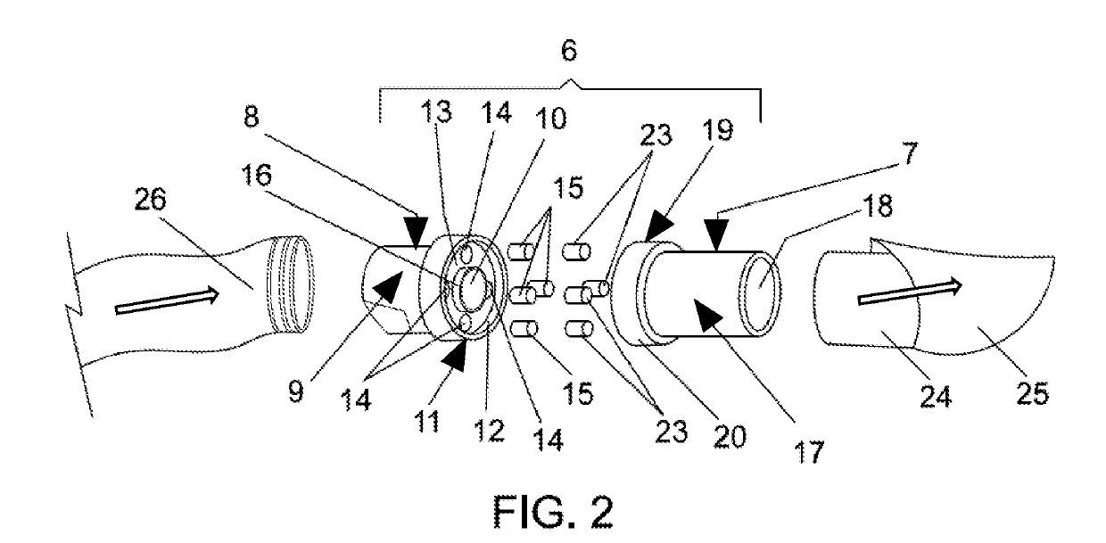
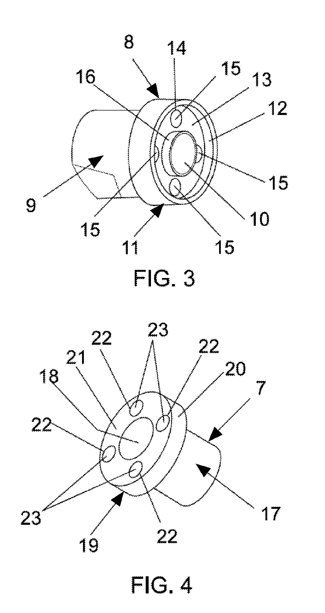
This patent describes an easy and fast way to connect air ducts in a pilot's helmet. It involves using magnets and a female connector with a larger diameter and a flat internal surface cavity. The male connector has a smaller diameter and a flat external surface. When the two connectors are brought together, the magnets in the female connector align with the magnets in the male connector, creating a secure and seamless connection. This improves the efficiency and safety of the air supply in the helmet.

Problems solved by technology

However, this type of connection has serious drawbacks, such as when the driver is inside the car it is difficult to connect the hose because the helmet is on, and when it is tightly coupled it is even more difficult to do so.
In particular, with the helmet on and with obstructed view, the pilot cannot see the connection.
Furthermore, there is no way to ensure a good connection of the air supply duct is maintained throughout a race or off-road experience.
Another problem is that, over time, the coupling parts of both the helmet and the hose or air supply duct, by the material with which they are manufactured, tend to suffer wear, and / or the hose or air supply duct no longer it is connected under pressure and the coupling is relieved, and / or it is no longer in the helmet because as the plastic material becomes larger and the coupling is no longer fixed.
Yet another problem that arises is that, at the time of an accident, when the pilot wants to leave the cab of the vehicle, he might not be able to disconnect the coupling ends (being made of flexible plastic material).
This is because the plastic might become stretched, damaged, or otherwise deformed, such that it tightens to the terminal of the helmet, and makes it very difficult to try to remove it.

Method used


Image

  • Forced-air helmet air coupling and system
  • Forced-air helmet air coupling and system
  • Forced-air helmet air coupling and system

Examples


Embodiment Construction

[0020]For a better understanding of the present disclosure, the follow detailed description of some of the embodiments thereof will be given, and shown in the appended drawings, which are for illustrative purposes, but are not limited to the following description. Accordingly, characteristic details of the forced-air helmet air coupling, system and method are clearly shown in the following description and in the illustrative drawings which are attached, the same reference signs serving to indicate the same or similar parts.

[0021]Aspects of the present disclosure generally pertain to an air coupling for a forced-air helmet to an air supply duct that may be easy and quick to attach and release. One purpose of the present disclosure is to make available an improved connection for forced-air helmet, and allows an easy connection and disconnection of the air supply ducts in the vehicle pilot's helmet without the need to apply force and without the need of tools. Another objective of the ...


PUM


Abstract

The disclosure relates to an improved connection for an air supply duct in a pilot helmet that includes a male connector and a female connector; wherein the female connector may include a tubular body defining an internal channel of air conduction and comprising an end connection section of greater diameter with an outgoing annular lip which defines a flat internal surface cavity in which a minimum of two magnets housed in at least two diametrically opposed holes are configured to couple with each other.

Description

BACKGROUNDTechnical Field[0001]The present disclosure generally pertains to vehicle helmet accessories, and is more particularly directed towards an air feed for an off-road vehicle helmet.Related Art[0002]In the vehicle (e.g., automotive) industry, accessories or safety devices may be used by the vehicle pilots / drivers / riders. One of the most important devices related to the safety of pilots is the helmet. The design, configuration and structure associated with the technology used in its construction have evolved significantly in recent times. The construction of the helmets for pilots must take into account their weight, the material of construction, the resistance of the materials, the conditions to which they are subjected as the “G” forces in the curves or in braking, in order to take care of the integrity of the pilots and avoid injury to the neck and head. Currently the helmets have a much higher hardness and their weight has dropped considerably (now weigh 1.25 kilos). The n...

Claims


Application Information

Patent Timeline
Patent Type & Authority Applications(United States)
IPC IPC(8): A42B3/28
CPCA42B3/286A42B3/283A42B3/225
Inventor HERNANDEZ TORRES, RENE ALEJANDRO
Owner HERNANDEZ TORRES RENE ALEJANDRO
Learn More