Turbine engine component with deflector

a turbine engine and deflector technology, applied in the direction of machines/engines, stators, mechanical equipment, etc., can solve the problems of reducing service life, requiring additional maintenance, and collecting excessive dust or particulates

Active Publication Date: 2018-12-20
GENERAL ELECTRIC CO
View PDF7 Cites 4 Cited by
  • Summary
  • Abstract
  • Description
  • Claims
  • Application Information

AI Technical Summary

Benefits of technology

The patent relates to a method to prevent cooling fluid from flowing in a turbine engine in a way that causes problems. The method involves using a deflector to direct the cooling fluid away from the engine's film hole, reducing the velocity of the cooling fluid and minimizing the negative effects on the engine.

Problems solved by technology

The cooling circuits can include one or more airflow element to enhance the cooling, however, such elements can lead to excessive collection of dust or particulate matter reducing service life or requiring additional maintenance.

Method used


Image

  • Turbine engine component with deflector
  • Turbine engine component with deflector
  • Turbine engine component with deflector

Examples


Embodiment Construction

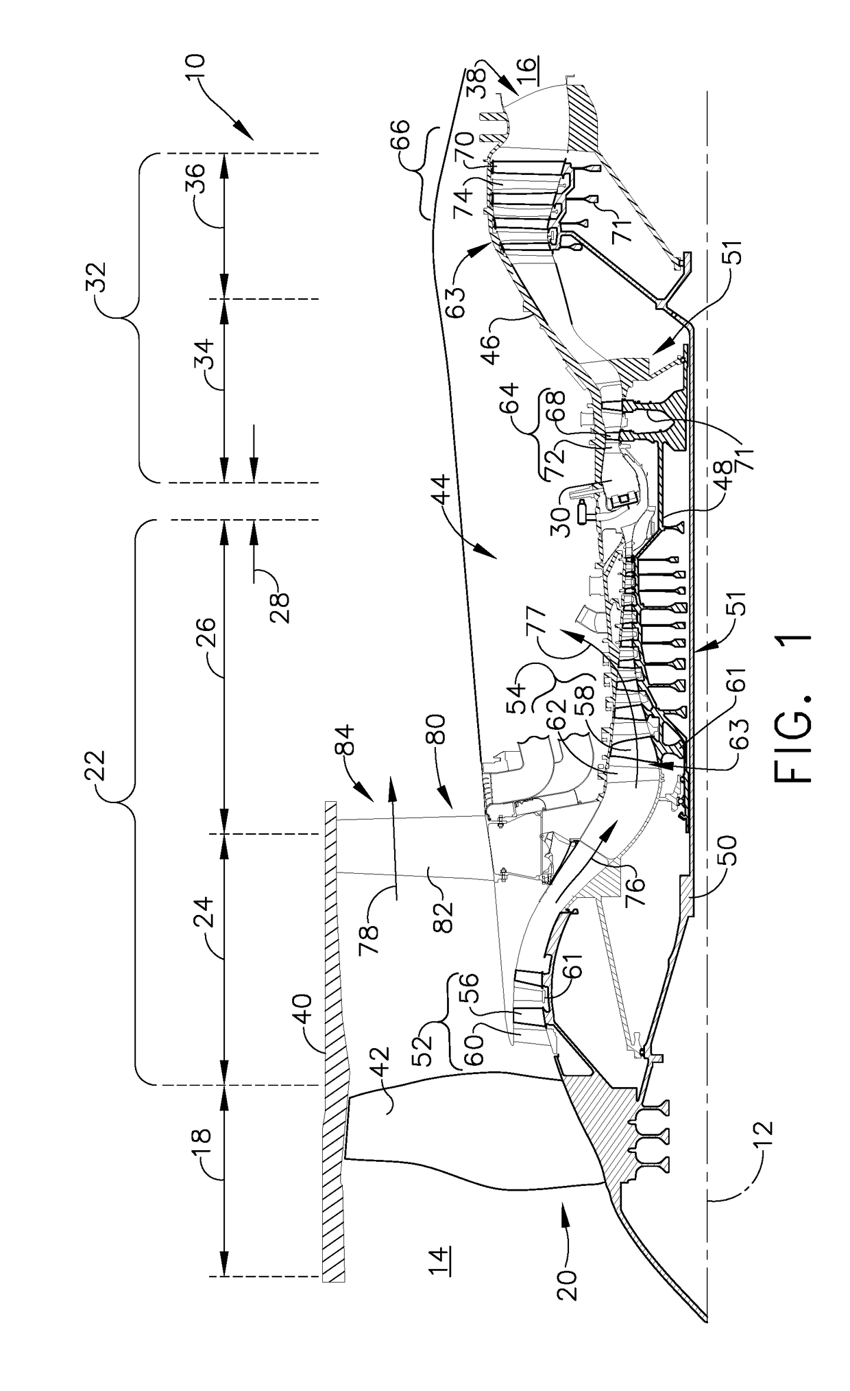
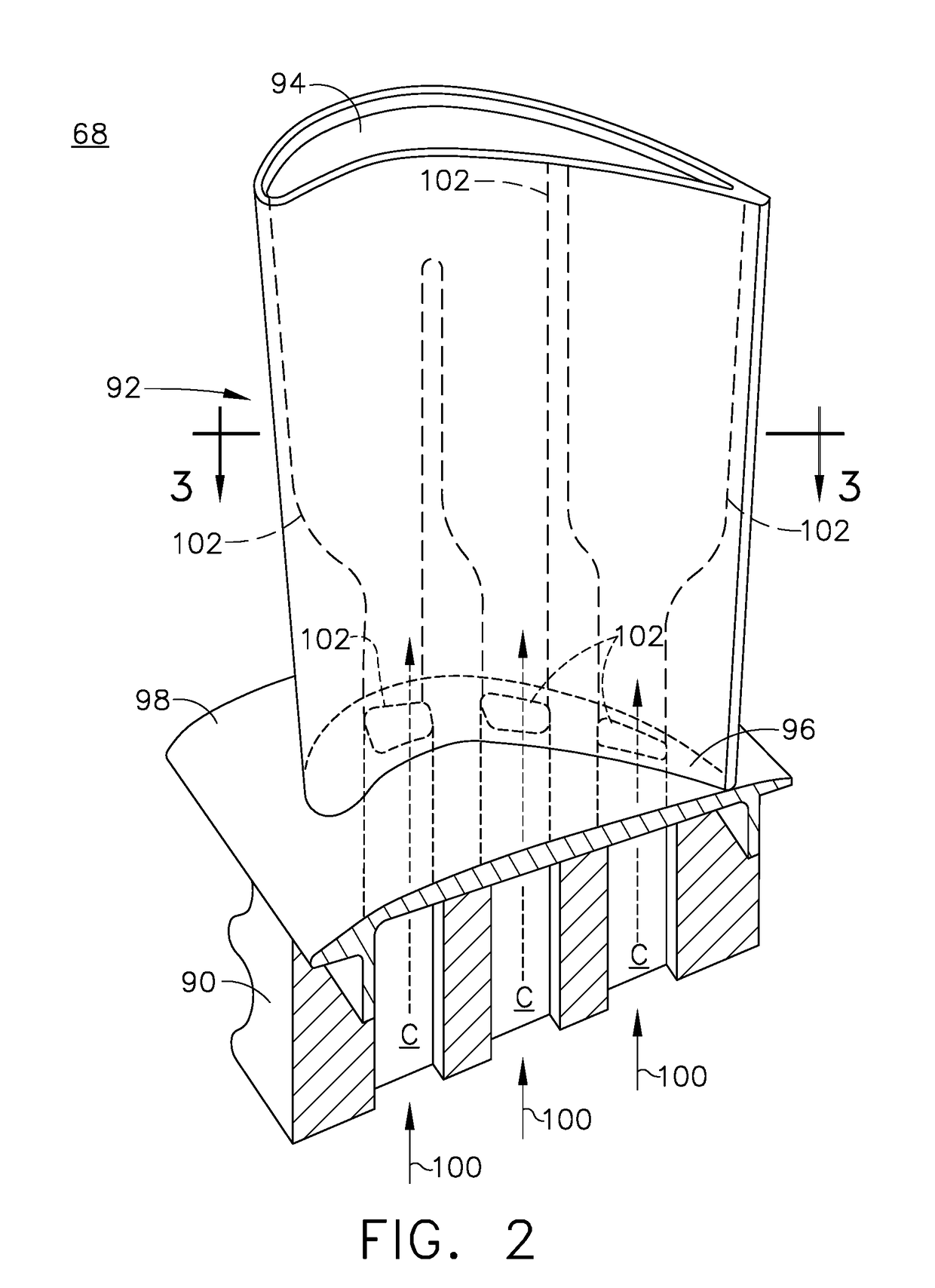
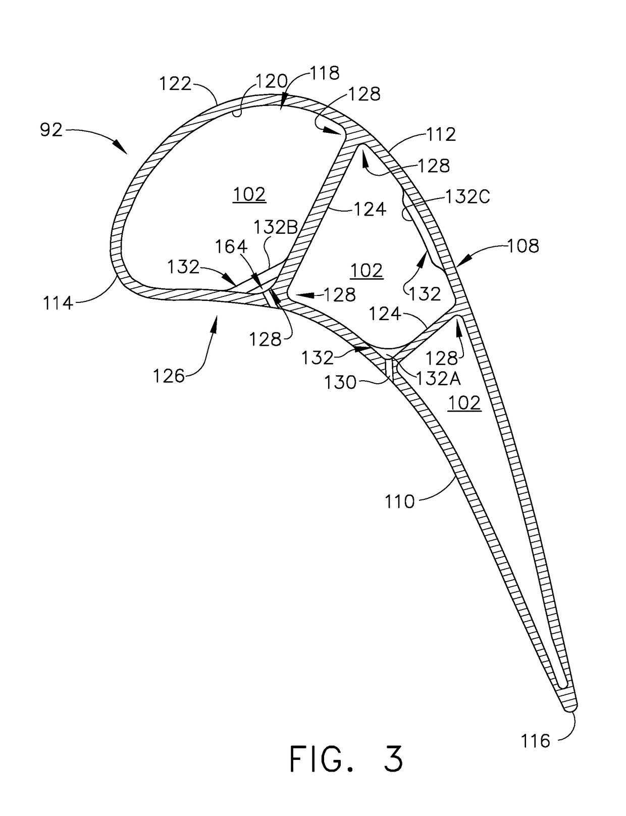
[0022]Aspects of the disclosure described herein are directed to airflow deflectors provided within an airfoil blade. For purposes of illustration, the present disclosure will be described with respect to the turbine for an aircraft gas turbine engine. It will be understood, however, that aspects of the disclosure described herein are not so limited and may have general applicability within an engine, including compressors, as well as in non-aircraft applications, such as other mobile applications and non-mobile industrial, commercial, and residential applications. Similarly, the aspects as described herein will have equal applicability to other engine components having film cooling and are not limited to airfoils or blades alone.

[0023]As used herein, the term “forward” or “upstream” refers to moving in a direction nearer to an origin of a flow of fluid relative to the direction of the local flow of fluid, such as air, or toward the engine inlet, or a component being relatively clos...


PUM


Abstract

An apparatus and method for a turbine engine for can include an engine component. The engine component can include an interior cooling passage at least partially defining a cooling circuit for passing a flow of cooling fluid through the component. Film holes provide for exhausting a portion of the cooling fluid to an exterior of the component, to form a cooling film along an exterior hot surface of the engine component. A deflector can be position within the cooling passage upstream form the film hole.

Description

BACKGROUND OF THE INVENTION[0001]Turbine engines, and particularly gas or combustion turbine engines, are rotary engines that extract energy from a flow of combusted gases passing through the engine onto a multitude of rotating turbine blades.[0002]Gas turbine engines for aircraft are designed to operate at high temperatures to maximize engine efficiency, so cooling of certain engine components, such as the high pressure turbine and the low pressure turbine, can be beneficial. Typically, cooling is accomplished by ducting cooler air from the high and / or low pressure compressors to the engine components that require cooling. Temperatures in the high pressure turbine are around 1000° C. to 2000° C. and the cooling air from the compressor is around 500° C. to 700° C. While the compressor air is a high temperature, it is cooler relative to the turbine air, and can be used to cool the turbine.[0003]Contemporary turbine blades generally include one or more interior cooling circuits for ro...

Claims


Application Information

Patent Timeline
IPC IPC(8): F01D5/18F01D5/14F01D9/02F01D25/12
CPCF01D5/186F01D5/147F01D9/02F05D2260/221F05D2220/30F05D2260/202F01D25/12F01D5/187F05D2240/126F05D2250/23F05D2250/13Y02T50/60
Inventor GALLIER, KIRK D.
Owner GENERAL ELECTRIC CO
Why Eureka
Try Eureka