Information processing apparatus, information processing method, and program
a technology of information processing apparatus and information processing method, applied in the field of information processing apparatus, information processing method, program, can solve the problems of inability of terminals to reproduce smoothly moving image data, insufficient band for moving image data encoded at a high rate, excessive band for moving image data encoded at a low rate, etc., to achieve smooth reproduction of data transmitted
- Summary
- Abstract
- Description
- Claims
- Application Information
AI Technical Summary
Benefits of technology
Problems solved by technology
Method used
Image
Examples
first embodiment
[0054]First, a first embodiment of the present technology will be described.
Network Configuration of System
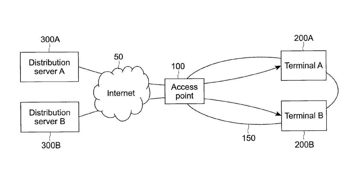
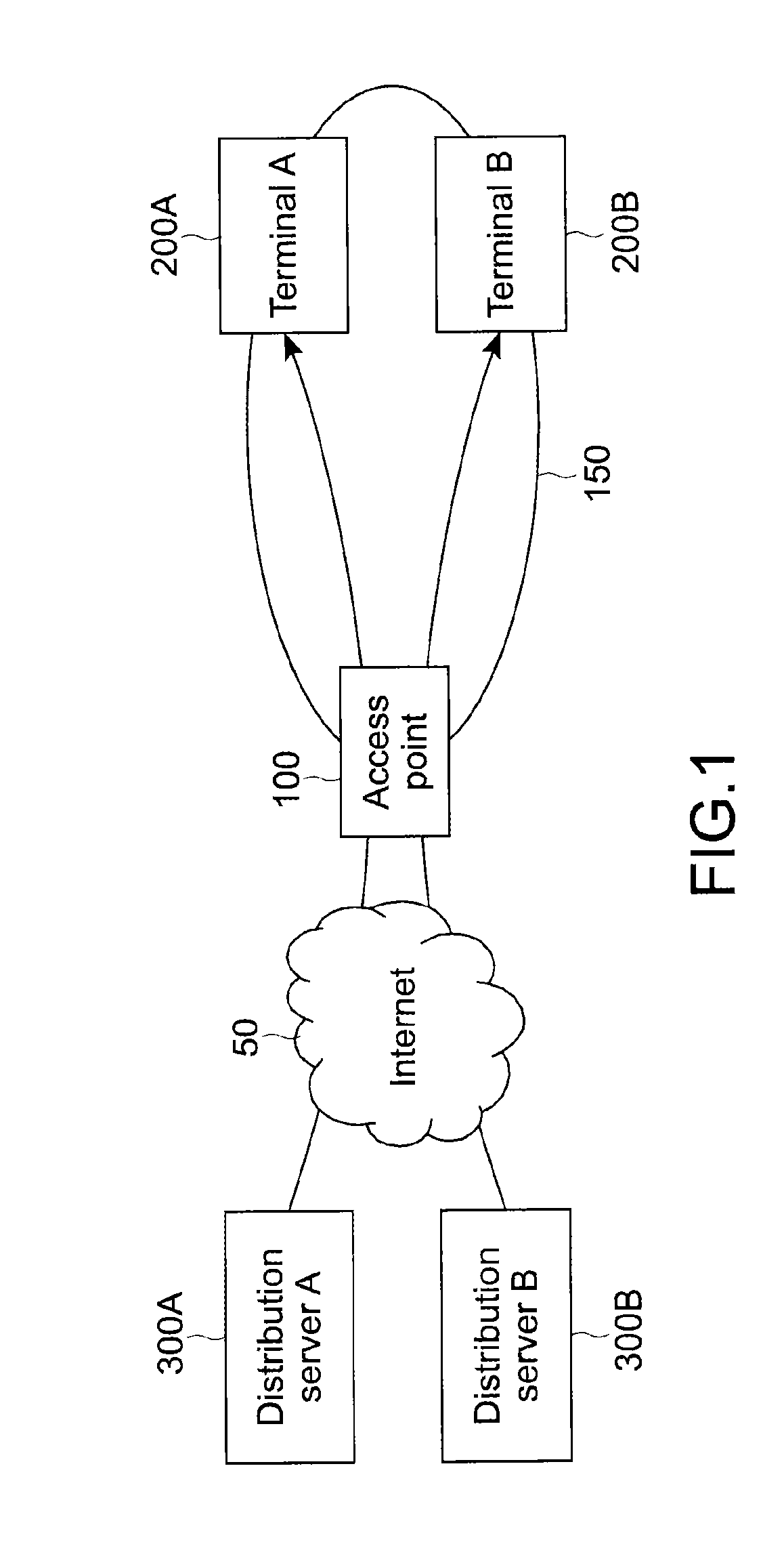
[0055]FIG. 1 is a diagram showing a network configuration of a system according to this embodiment.
[0056]As shown in the figure, this system includes a distribution server 300, an access point 100, and a terminal 200. A plurality of distribution servers 300 can be present. In the figure, two distribution servers 300A and 300B are shown. However, three or more distribution servers 300 may be present. Further, a plurality of terminals 200 can be present for one access point 100. In the figure, two terminals 200A and 200B are shown. However, three or more terminals 200 may be connected to one access point 100.
[0057]Although the distribution servers 300 are provided on the Internet 50, for example, and distributes moving image data to the terminals 200. The moving image data is transmitted by progressive download. An encoding rate of the moving image data may differ depending on th...
second embodiment
[0135]Next, a second embodiment of the present technology will be described. In this embodiment and the following embodiments, the parts having the same functions as those in the first embodiment will be denoted by the same reference symbols and descriptions thereof will be omitted or simplified and points different from those in the first embodiment will be mainly described.
[0136]In the first embodiment, the access point 100 regularly obtains the buffer time information from each terminal 200. On the other hand, in this embodiment, the access point 100 calculates the buffer time of each terminal 200 by itself.
Module Configuration of Server, Access Point, and Terminal
[0137]FIG. 15 is a block diagram showing a configuration of software modules and a database of a distribution server 300, the access point 100, and the terminal 200 in this embodiment.
[0138]As shown in the figure, in this embodiment, compared with the system shown in FIG. 4 as the first embodiment, the access point 100 ...
third embodiment
[0157]Next, a third embodiment of the present technology will be described.
[0158]In the first and second embodiments, the access point 100 uses the priority control method, for example, IEEE802.11e or a ToS field in an IP header in order to preferentially transmit the packet to the priority terminal. However, in this embodiment, an access point 100 dynamically changes a band allocated for each terminal 200 in a wireless LAN 150 according to an encoding rate of moving image data addressed to each terminal 200, to thereby preferentially transmit a packet addressed to the priority terminal.
Module Configuration of Server, Access Point, and Terminal
[0159]FIG. 18 is a block diagram showing a configuration of a software module and a database of a distribution server 300, the access point 100, and the terminal 20 in this embodiment.
[0160]As shown in the figure, in this embodiment, the access point 100 includes a band control module 106 instead of the priority control flag setting module 102...
PUM
 Abstract
Description
Claims
Application Information
 - R&D
- Intellectual Property
- Life Sciences
- Materials
- Tech Scout
- Unparalleled Data Quality
- Higher Quality Content
- 60% Fewer Hallucinations
Browse by: Latest US Patents, China's latest patents, Technical Efficacy Thesaurus, Application Domain, Technology Topic, Popular Technical Reports.
© 2025 PatSnap. All rights reserved.Legal|Privacy policy|Modern Slavery Act Transparency Statement|Sitemap|About US| Contact US: help@patsnap.com


