Battery terminal

Active Publication Date: 2017-05-04
SUMITOMO WIRING SYST LTD
View PDF0 Cites 2 Cited by
  • Summary
  • Abstract
  • Description
  • Claims
  • Application Information

AI Technical Summary

Benefits of technology

The patent text describes a fastening assembly for a battery post. The assembly includes fastening pieces that are designed to be deformed and held in close contact with the battery post. This design allows for stable deformation of the fastening pieces at a constant height, which ensures reliable connection to the battery post. The fastening pieces are only formed on the upper member, which reduces the required operational force for deformation and improves operability in connection to the battery post. Overall, the patent text describes a technical solution for secure and easy battery post fastening.

Problems solved by technology

Thus, a large operation force is necessary in fastening the bolt and the nut, causing a problem that operability in connection to the battery post is poor.
According to this configuration, since the fastening pieces can be positioned with respect to the battery post, they are unlikely to be held in close contact with the battery post in a non-uniform manner in a circumferential direction.

Method used


Image

  • Battery terminal
  • Battery terminal
  • Battery terminal

Examples


first embodiment

Functions of First Embodiment

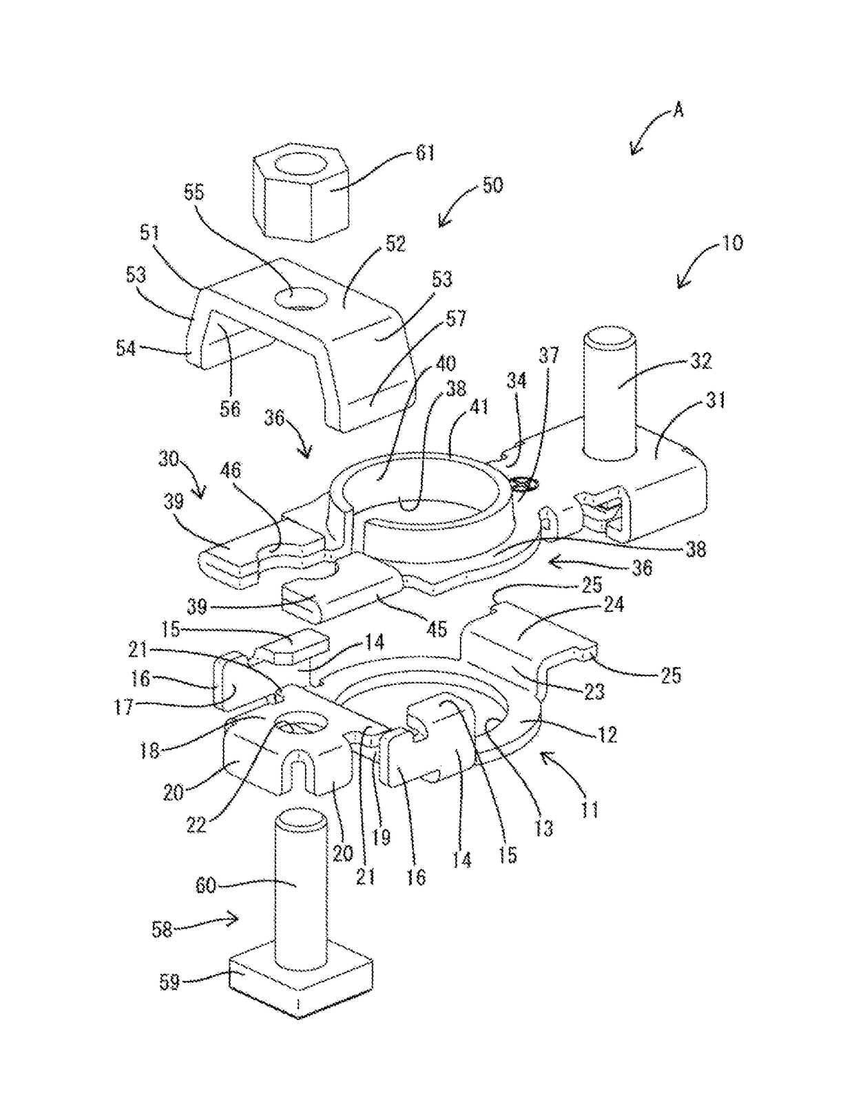
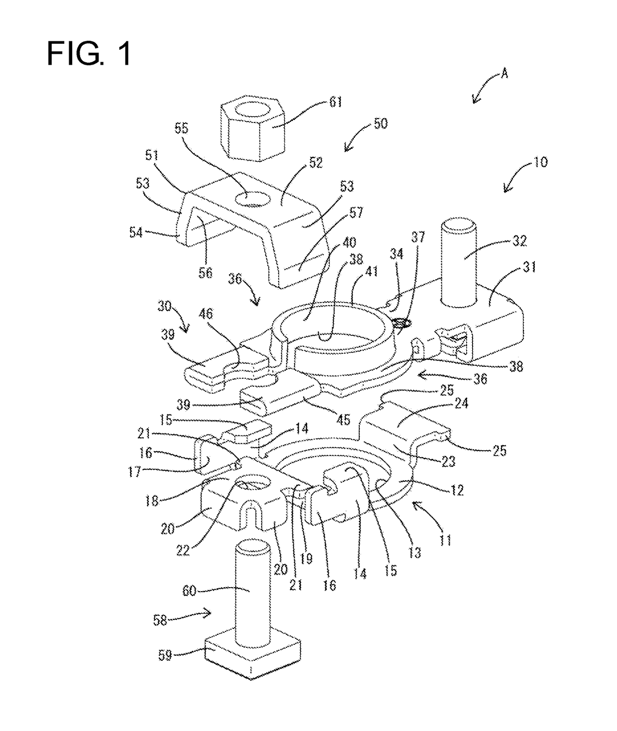
[0061]The cam member 51, the fastening bolt 58 and the nut 61 are temporarily assembled with the terminal main body 10 in advance before connection to the battery post P. In temporarily assembling, the male screw portion 60 of the fastening bolt 58 is inserted into the through hole 22 from below the supporting plate portion 18 and the base 59 is brought into contact with the lower surface of the supporting plate portion 18 and fitted to the rotation preventing portions 20 as shown in FIGS. 8 and 9. In this way, the fastening bolt 58 is held with the rotation thereof with respect to the lower member 11 and the upper member 30 restricted.

[0062]The cam member 51 is mounted to cover the pair of pressure receiving portions 39 from above before or after the fastening bolt 58 is inserted through the supporting plate 18. With the cam member 51 mounted, the left and right pressure receiving portions 39 are located such that the arcuate surfaces 45 thereof face up...

fourth embodiments

Second to Fourth Embodiments

[0081]Next, second to fourth specific embodiments of the present invention are described with reference to FIGS. 16 to 18. Note that the substantially same or similar components as in the first embodiment are denoted by the same reference signs and the structures, functions and effects thereof are not described.

[0082]A cam member 70 constituting or forming part of a battery terminal B of the second embodiment includes vertical walls 71 extending down longer than in the first embodiment, and both inner and outer side surfaces of the vertical walls 71 serve as vertical contact surfaces 72. Inclination restricting portions 73 are arranged both at positions where they face the vertical contact surfaces 72 on the outer side surfaces while laterally sandwiching the cam member 70 as in the first embodiment and at positions where they substantially face the vertical contact surfaces 72 on the inner side surfaces of the vertical walls 71. That is, since one vertic...


PUM


Abstract

A battery terminal (A) includes a lower member (11) to be fit to a battery post (P) having an axis line extending in a vertical direction while being positioned with respect to the battery post (P) and an upper member (30) arranged above the lower member (11). Two fastening pieces (36) are formed only on the upper member (30) and are deformable to be held in close contact with an outer periphery of the battery post (P). A fastening member (50) is provided for deforming the fastening pieces (36) so that the fastening pieces (36) are held in close contact with the battery post (P).

Description

BACKGROUND[0001]1. Field of the Invention[0002]The invention relates to a battery terminal.[0003]2. Description of the Related Art[0004]Japanese Unexamined Patent Publication No. 2002-184389 discloses a battery terminal with a terminal main body, a bracket, a bolt and a nut. The terminal main body includes pairs of fastening pieces capable of sandwiching a battery post. Inclined surfaces formed on the bracket are held in contact with outer side edges of the pairs of fastening pieces. When the bracket is displaced by fastening the bolt and nut, the pairs of fastening pieces are brought closer by the inclined surfaces of the bracket and held in close contact with the outer peripheral surface of the battery post.[0005]In fastening the bolt and the nut, both the fastening pieces of a lower part and those of an upper part are brought closer in the above-described battery terminal. Thus, a large operation force is necessary in fastening the bolt and the nut, causing a problem that operabi...

Claims


Application Information

Patent Timeline
IPC IPC(8): H01M2/30H01M50/567
CPCH01M2/30H01M50/567Y02E60/10H01R11/283
Inventor TSUKIYOSHI, KEIICHI
Owner SUMITOMO WIRING SYST LTD
Why Eureka
Try Eureka