
Method of refraction angle mapping of earth's limb

a technology of refraction angle and mapping method, applied in the field of refraction angle profile generation, can solve the problems of limited temporal and spatial coverage of weather balloon network, limited gps-based temperature and pressure profile, and high cost of remote optical sensing instruments. achieve the effect of efficient and comprehensiv

Active Publication Date: 2017-03-16
GLOBAL ATMOSPHERIC TECH & SCI INC
View PDF4 Cites 6 Cited by
  • Summary
  • Abstract
  • Description
  • Claims
  • Application Information

AI Technical Summary

Benefits of technology

The present invention provides a efficient and comprehensive method for generating global refraction angle fields at high altitudes. This can be useful in various applications such as optical instruments and imaging technologies.

Problems solved by technology

Unfortunately, remote optical sensing instruments are generally very expensive.
Though accurate, they require satellite receivers and often produce slanted profiles.
GPS-based temperature and pressure profiles are limited by the directionality of GPS transmitters and the occultation between GPS and receiver platforms.
Even with this seemingly large number of daily weather balloon launchings, the weather balloon network is limited in terms of temporal and spatial coverage, especially over oceans.

Method used


Image

  • Method of refraction angle mapping of earth's limb
  • Method of refraction angle mapping of earth's limb
  • Method of refraction angle mapping of earth's limb

Examples


Embodiment Construction

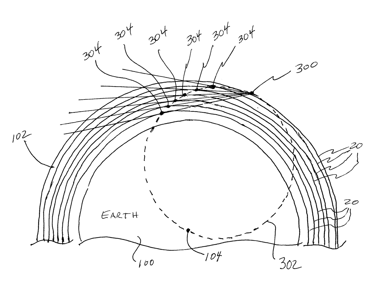
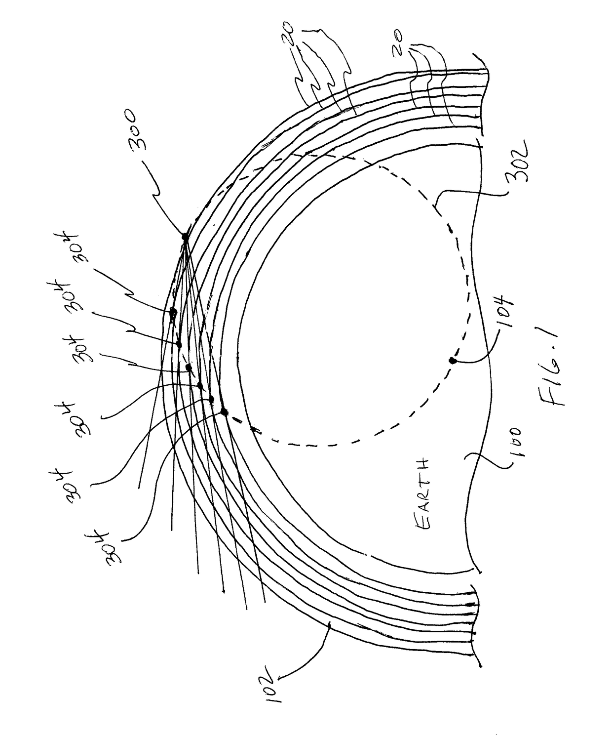
[0017]Referring now to the drawings and more particularly to FIG. 1, a portion of the Earth is shown and is referenced generally by numeral 100. Surrounding or encasing Earth 100 is its atmosphere 102 that refracts light as the light passes through. The amount of refraction increases with density of the atmosphere. Accordingly, in general, light is refracted more near the surface of Earth 100 than at upper regions of the atmosphere. In regions beyond the atmospheric limb or space, light is not refracted.

[0018]Prior to explaining the method of the present invention, a few concepts will be explained. Continuing to refer to FIG. 1, various altitudes above Earth 100 are indicated by solid lines 200 encircling Earth 100 with an observation point being indicated by numeral 300 at an upper altitude. From observation point 300, a circle 302 can be defined whose diameter spans from observation point 300 to the center 102 of Earth 100. Lines extending from observation point 300 to tangent poi...


PUM


Abstract

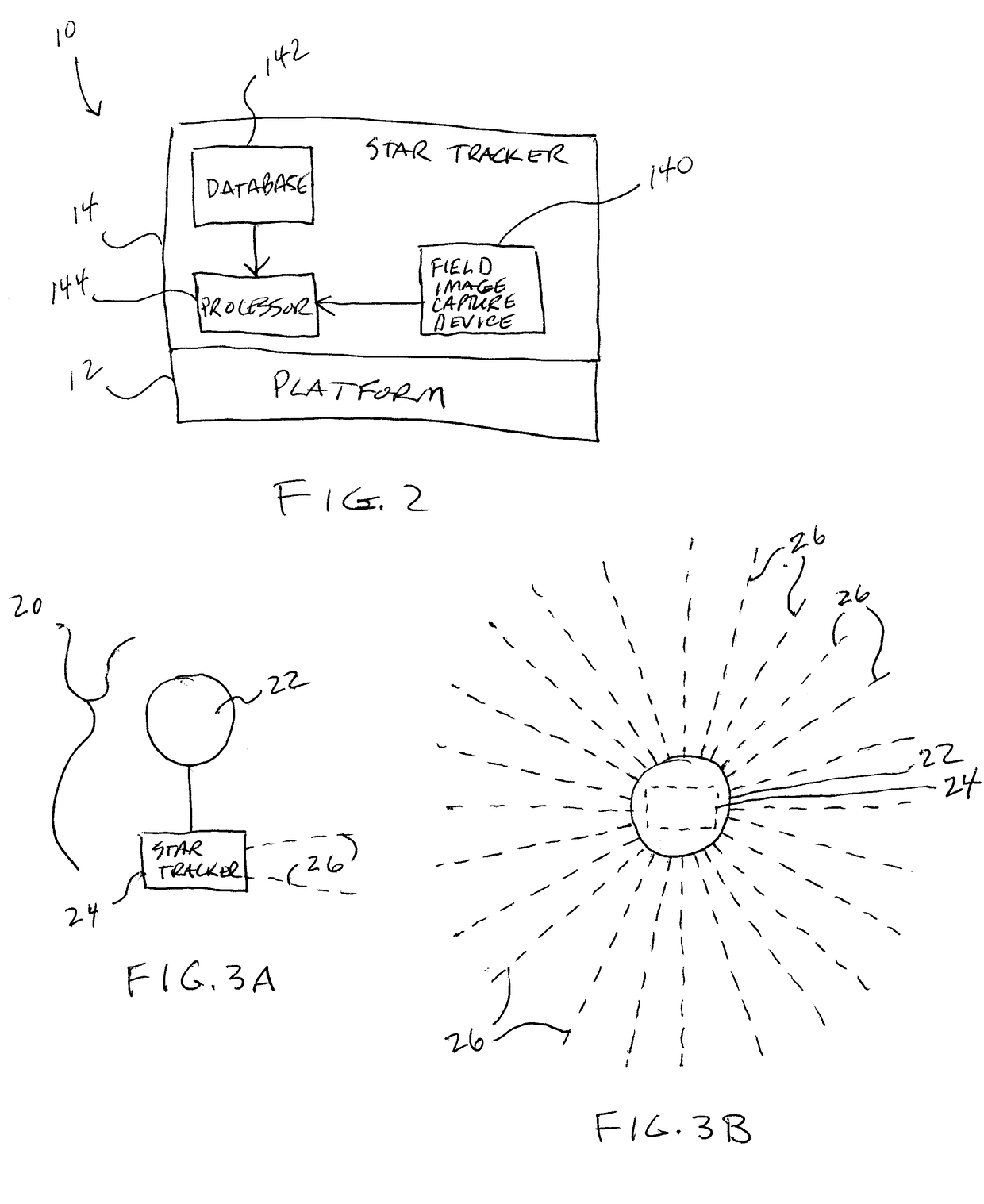
Refraction angles in a planet's atmosphere are mapped using a database of known star locations and a field imager onboard a platform above the planet. The field imager is positioned to observe a region that includes a portion of the planet's atmospheric limb. A star field image is captured for the region. The star field image includes stars within the field imager's field-of-view. Using the field imager and the database, a modeled star field image is generated that is matched in size to the field-of-view associated with the star field image. The modeled star field image defines absolute locations of stars corresponding to stars appearing in the field imager's field-of-view. Differences between the absolute locations and locations of the images of stars are indicative of a limb refraction angle field.

Description

FIELD OF THE INVENTION[0001]The invention relates generally to refraction angle profile generation, and more particularly to a method of generating a map of refraction angles in the Earth's limb using star field images.BACKGROUND OF THE INVENTION[0002]Currently, a variety of satellite sensors can make high altitude (i.e., above the tropopause) temperature and pressure measurements. For example, many remote optical sensors can provide moderate daily coverage using emission measurements. Unfortunately, remote optical sensing instruments are generally very expensive.[0003]Temperature and pressure profiles can also be derived from Global Positioning System (GPS) measurements using orbiting receivers of signals from GPS transmitters. Though accurate, they require satellite receivers and often produce slanted profiles. GPS-based temperature and pressure profiles are limited by the directionality of GPS transmitters and the occultation between GPS and receiver platforms.[0004]The most comp...

Claims


Application Information

Patent Timeline
IPC IPC(8): G06K9/00G01C21/24G06K9/62G06V20/13
CPCG06K9/0063G01C21/24G06K9/6212G06V20/13
Inventor GORDLEY, LARRY L
Owner GLOBAL ATMOSPHERIC TECH & SCI INC
Learn More