Post-Hole Digger with Foot Rests

a technology of footrests and digging tools, which is applied in the field of digging tools, can solve the problems of affecting soil fertility, tiring and inefficient use of conventional post-hole digging tools, and affecting soil fertility

Active Publication Date: 2016-10-06
HUDSON ANDREW JOHN +1
View PDF1 Cites 7 Cited by
  • Summary
  • Abstract
  • Description
  • Claims
  • Application Information

AI Technical Summary

Benefits of technology

This patent describes a device called a foot rest for use with a post-hole dagger. It consists of two parts that attach to the ends of the machine. These parts can connect together when the machine's arms are upright. The foot rest doesn't stick out from the hole, but it has an angle to make sure the person's feet stay on top of it. Some versions also have a flat surface on both sides, making them more comfortable for different users.

Problems solved by technology

The technical problem addressed in this patent text relates to improving the efficiency and comfort of using traditional post-hole diggers by allowing users to better utilize their legs and feet during operation. Previous attempts at solving this issue resulted in tools that were uncomfortable to wear or had limited effectiveness due to design flaws such as excessive weight or difficulty in accessing soil.

Method used


Image

  • Post-Hole Digger with Foot Rests
  • Post-Hole Digger with Foot Rests
  • Post-Hole Digger with Foot Rests

Examples


Embodiment Construction

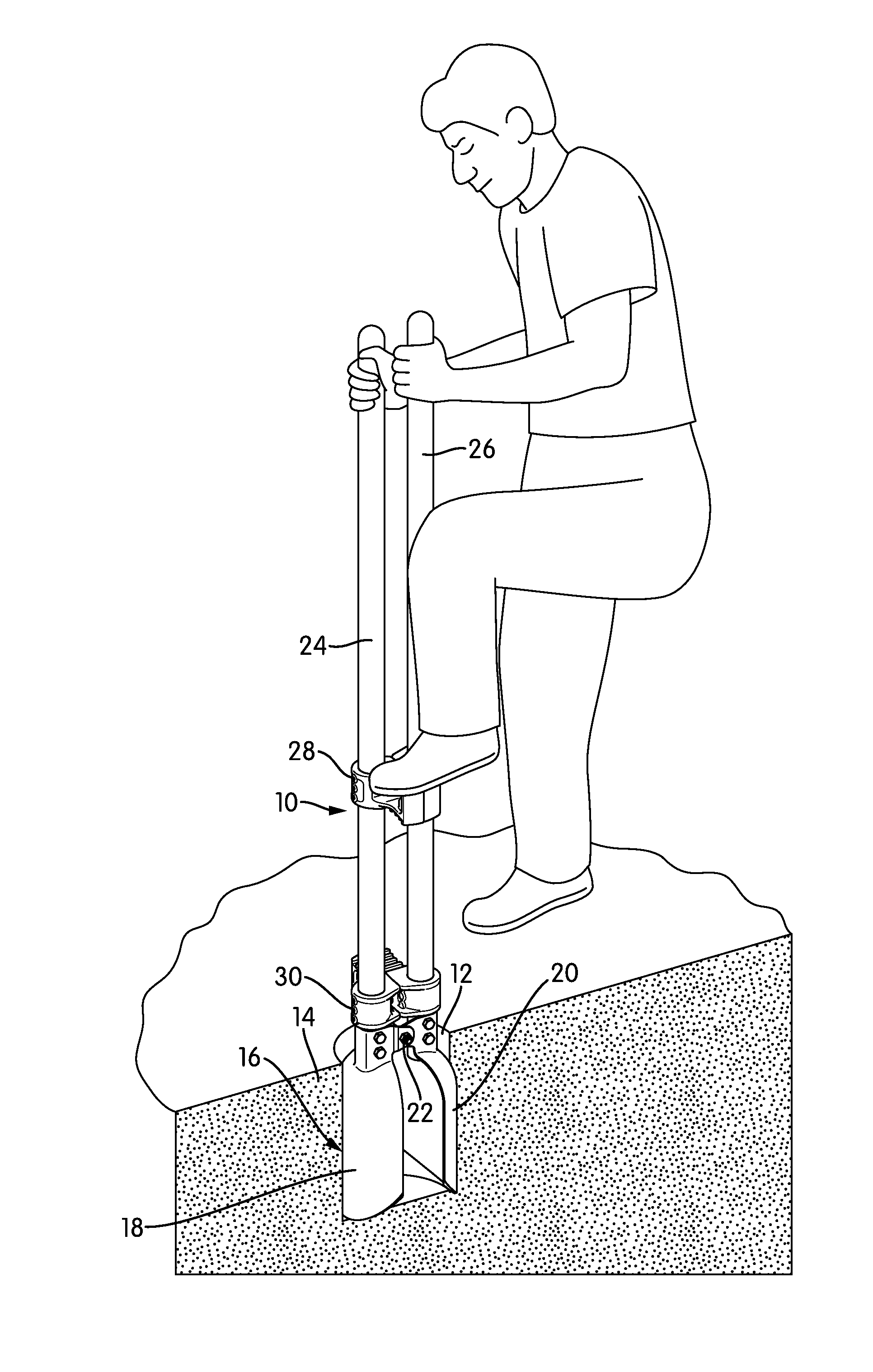
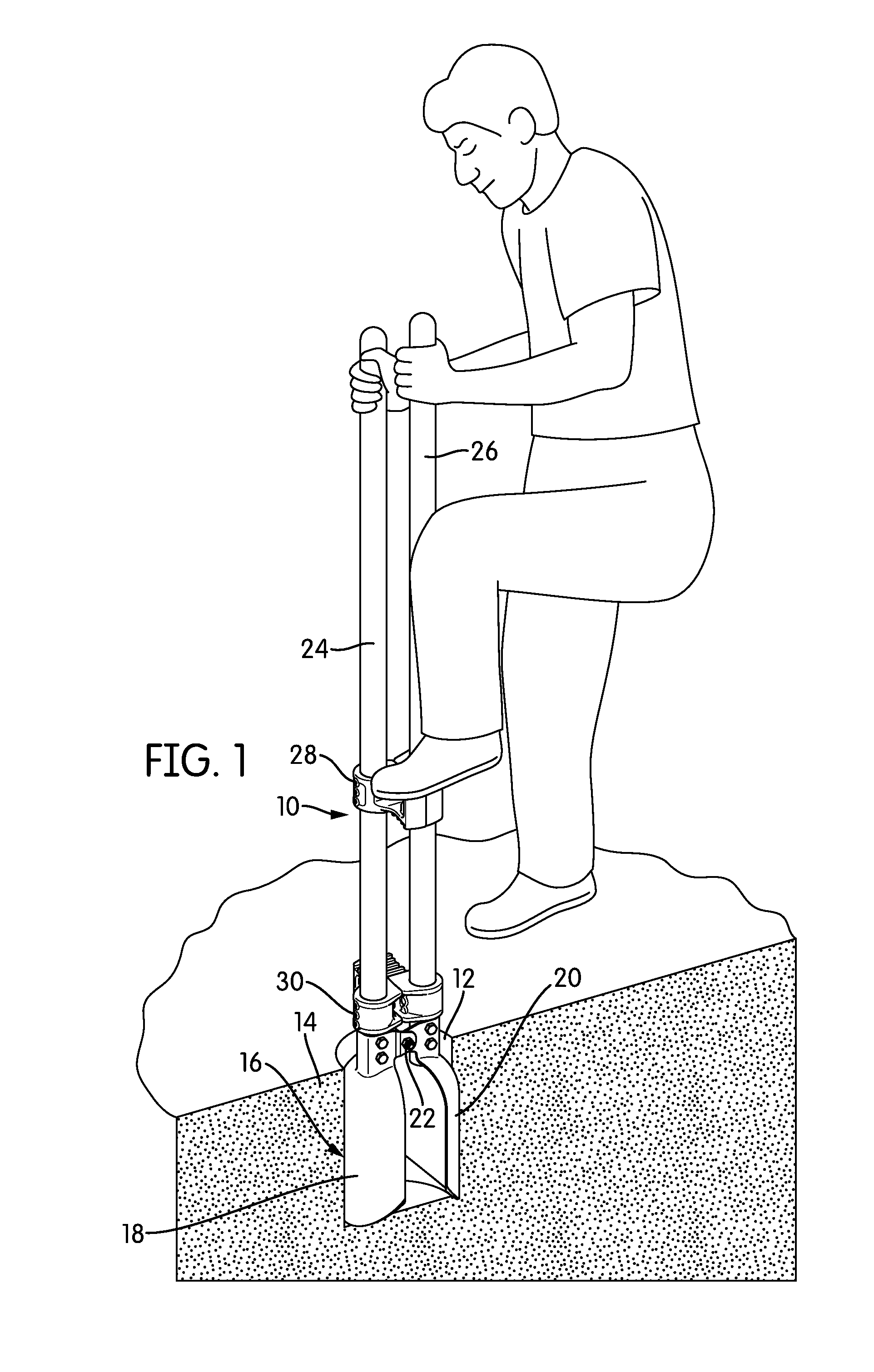
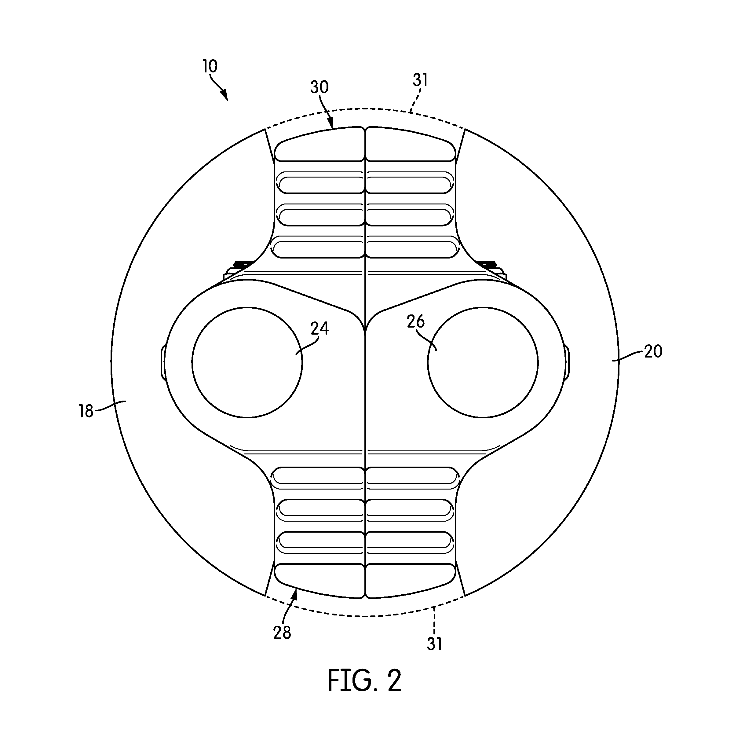
[0018]FIG. 1 is a perspective view of a post-hole digging tool, generally indicated at 10, according to one embodiment of the invention. The tool 10 is shown in FIG. 1 in use, digging a hole 12 in soil 14. The tool head 16 comprises two downwardly-extending, rounded digging blades 18, 20 that face one another and are connected together at a hinge 22, which pivots to allow the two digging blades 18, 20 to move closer together and farther apart. Each of the digging blades 18, 20 is connected to an individual shaft 24, 26 that, in the view of FIG. 1, extends vertically.

[0019]The tool 10 has a pair of foot rests 28, 30 spaced from one another along the length of the shafts 24, 26. Each foot rest 28, 30 extends in a different direction. The tool 10 may include any number of foot rests 28, 30 spaced from one another along the length of the shafts 24, 26. In fact, if a particularly deep hole 12 is to be dug, it may be helpful to have three or four foot rests 28, 30 present. The presence of...


PUM


Abstract

A foot rest for a post-hole digger and post-hole diggers using the foot rest are disclosed. The foot rest includes two portions, one attached to each shaft of the post-hole digger. The two portions have structure that allows them to engage one another when the two shafts of the post-hole digger are vertical. The foot rest does not extend beyond the bore diameter of the post-hole digger. Thus, in order to keep the user's feet on the relatively short foot rest, the contact surface of the foot rest may be angled. In some embodiments, the foot rest may be symmetrical, so that either side may be used as the upper surface. A post-hole digger including the foot rests typically includes at least two foot rests, spaced from one another and facing different directions along the shafts of the tool.

Description


Claims


Application Information

Patent Timeline
Owner HUDSON ANDREW JOHN
Why Eureka
Try Eureka