
Multipurpose Charging and Display Stand for a Computerized Wristwatch

a charging and display stand technology, applied in the field of multi-purpose charging and display stands for computerized wristwatches, can solve the problems of not allowing efficient display and charging of smartwatches, affecting the display effect of the watch, so as to facilitate viewing and access, facilitate the charging of the computerized wristwatch, and facilitate the effect of the display screen

Inactive Publication Date: 2016-09-08
KIDAKARN MICHAEL
View PDF20 Cites 45 Cited by
  • Summary
  • Abstract
  • Description
  • Claims
  • Application Information

AI Technical Summary

Benefits of technology

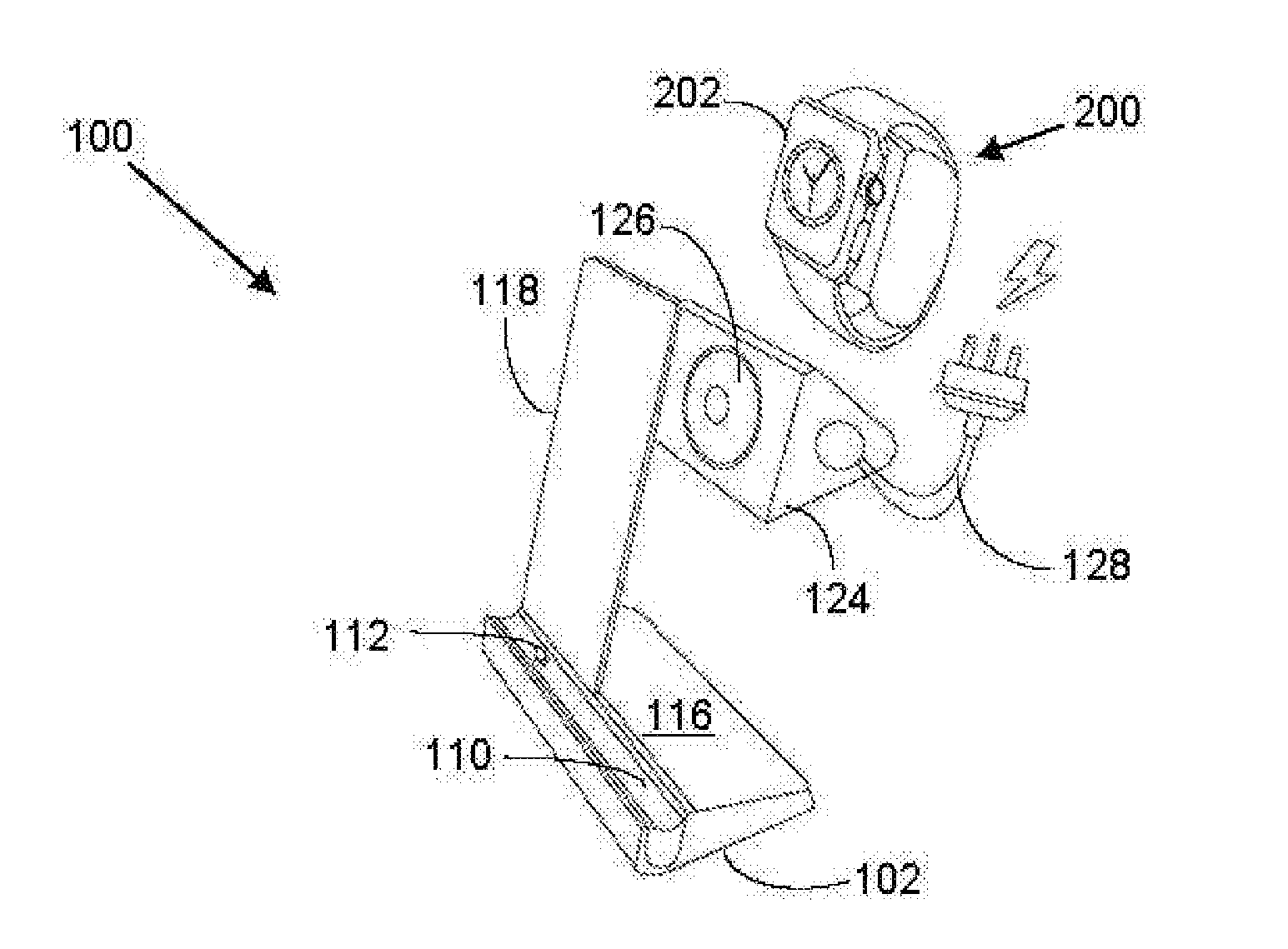
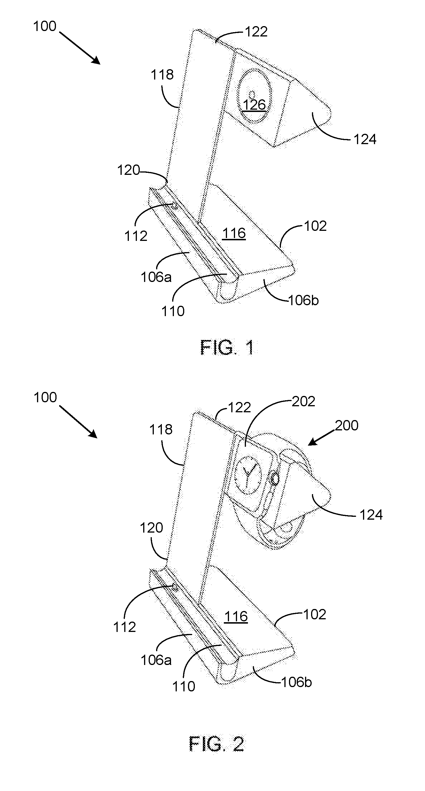
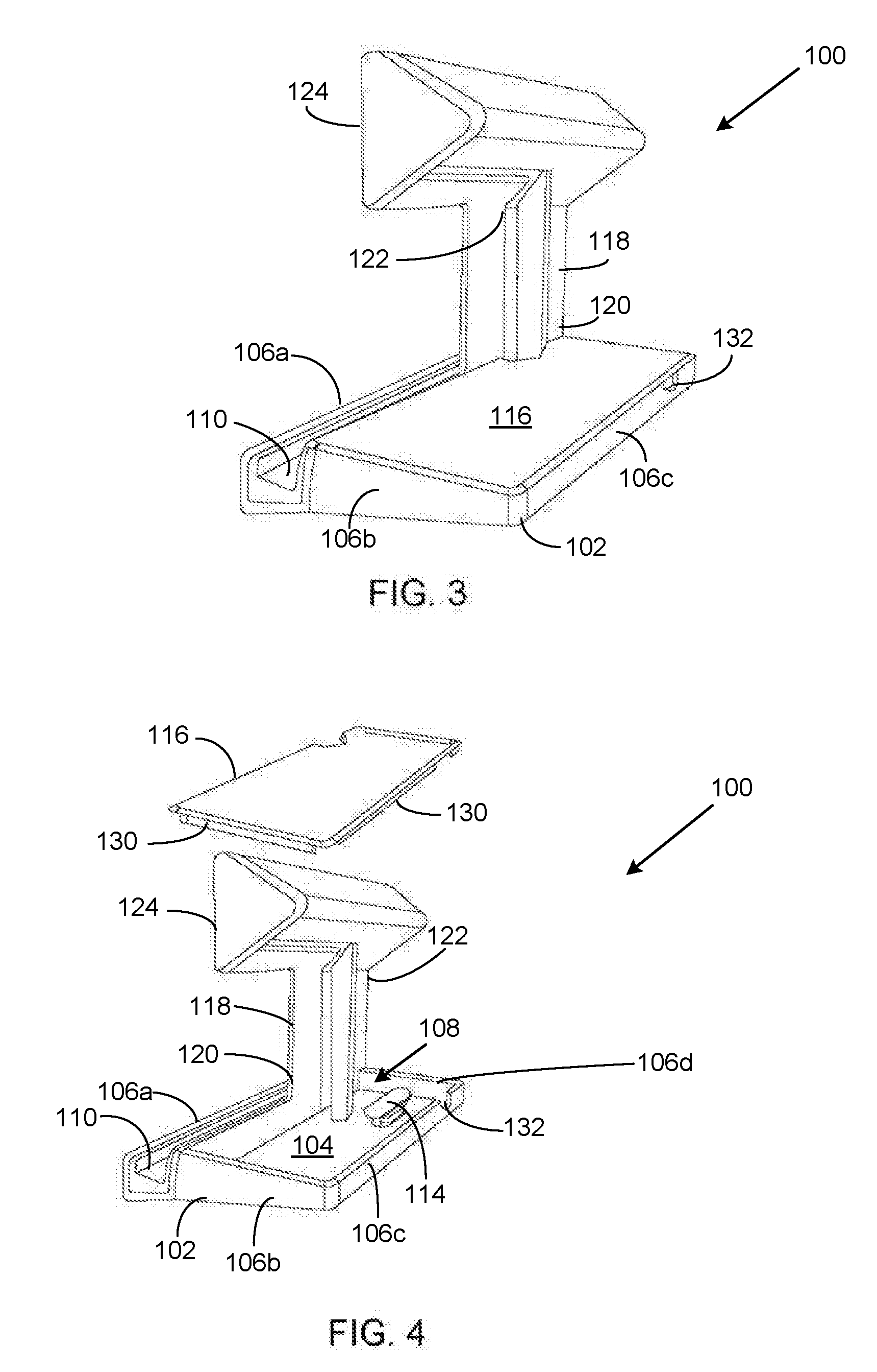
The patent is about a stand that can hold a computerized wristwatch and allow it to be viewed and charged easily. The stand has an adjustable mounting mechanism for the watch, a foundation that holds it securely, and a moving arm that allows for viewing and charging. The arm has a soft material to protect the watch from cold temperatures, and a power cable to charge it. This stand serves multiple purposes and makes it easy to view and access the components on the wristwatch.

Problems solved by technology

Charging is preferred because replacing the rechargeable battery can be problematic.
For the most part, a replacement of the rechargeable battery requires taking the smartwatch apart and disturbing the internal hardware.
The problem with these display and charging devices is that they do not allow for efficient display and charging of the smartwatch.

Method used


Image

  • Multipurpose Charging and Display Stand for a Computerized Wristwatch
  • Multipurpose Charging and Display Stand for a Computerized Wristwatch
  • Multipurpose Charging and Display Stand for a Computerized Wristwatch

Examples


Embodiment Construction

[0050]The following detailed description is merely exemplary in nature and is not intended to limit the described embodiments or the application and uses of the described embodiments. As used herein, the word “exemplary” or “illustrative” means “serving as an example, instance, or illustration.” Any implementation described herein as “exemplary” or “illustrative” is not necessarily to be construed as preferred or advantageous over other implementations. All of the implementations described below are exemplary implementations provided to enable persons skilled in the art to make or use the embodiments of the disclosure and are not intended to limit the scope of the disclosure, which is defined by the claims. For purposes of description herein, the terms “first,”“second,”“left,”“rear,”“right,”“front,”“vertical,”“horizontal,” and derivatives thereof shall relate to the invention as oriented in FIG. 1. Furthermore, there is no intention to be bound by any expressed or implied theory pre...


PUM


Abstract

A multipurpose charging and display stand is configured to: retain a computerized wristwatch, such as an Apple™ and a Lightningsmartwatch, in multiple vantage points to enable facilitated access to components on the computerized wristwatch, allow for charging of the computerized wristwatch through induction or direct cables, and allow for adjustable mounting of the computerized wristwatch to facilitate viewing of a display screen. The stand also enables compatible communication devices and accessories to communicate with the computerized wristwatch. A base forms a foundation for the stand and includes a cavity for storage of a power cable and other items. The base supports a post that extends at an angle. A leather arm rotatably joins with the post at a perpendicular orientation. The arm includes an inductive charging member that mates with the computerized wristwatch for charging. Alternatively, a power cable extends form the arm to charge the computerized wristwatch.

Description

CROSS REFERENCE OF RELATED APPLICATIONS[0001]This application claims the benefits of U.S. provisional application No. 62129913 filed Mar. 8, 2015 and entitled SMARTWATCH CHARGING AND DISPLAY STAND, which provisional application is incorporated by reference herein in its entirety.FIELD OF THE INVENTION[0002]The present invention relates generally to a multipurpose charging and display stand for a computerized wristwatch. More so, a multipurpose charging and display stand retains a computerized wristwatch, such as a smartwatch, at multiple vantage points to enable facilitated access to components on the computerized wristwatch, allows for charging of the computerized wristwatch through induction or direct cables, and allows for adjustable mounting of the computerized wristwatch to facilitate viewing of a display screen on the smart watch and compatible communication devices that are in communication with the smartwatch.BACKGROUND OF THE INVENTION[0003]The following background informat...

Claims


Application Information

Patent Timeline
IPC IPC(8): H02J7/02G04G19/02A47F7/02H02J7/00
CPCH02J7/025A47F7/022G04G19/02H02J7/0042H02J7/0044H02J50/10
Inventor KIDAKARN, MICHAEL
Owner KIDAKARN MICHAEL
Learn More