Connector and inspection tool

a technology of inspection tool and connector, which is applied in the direction of connection, electrical apparatus, coupling device connection, etc., can solve the problems of affecting inspection reliability, affecting inspection reliability, and easy displacement of relative positions of inspection tool and inspection tool from a proper position, so as to enhance positioning reliability, avoid complicated housing structure, and maintain high inspection reliability

Active Publication Date: 2015-12-31
SUMITOMO WIRING SYST LTD
View PDF6 Cites 2 Cited by
  • Summary
  • Abstract
  • Description
  • Claims
  • Application Information

AI Technical Summary

Benefits of technology

The patent describes an inspection tool for inspecting the inserted state of terminal fittings. The tool is positioned by excessive deflection regulating pieces, which are provided side by side in the width direction at the positions corresponding to the locking lances. This design eliminates the need for dedicated positioning portions in the housing, simplifying the structure. The excessive deflection regulating pieces guide the inspection tool, improving positioning reliability. The tool can be divided into sets with smaller intervals between adjacent excessive deflection regulating pieces, ensuring a large wall thickness for the outer side walls of the tool. This improves the strength of the tool and allows for miniaturization. Overall, this design provides a strong and reliable inspection tool with improved positioning accuracy.

Problems solved by technology

Additionally, relative positions of the terminal fitting and the inspection tool easily are displaced from a proper position at the time of inspection.
A displacement of the relative positions of the terminal fitting and the inspection tool from the proper position may adversely affect inspection reliability.
A housing may have positioning portions for positioning the inspection tool, but this complicates the housing.

Method used


Image

  • Connector and inspection tool
  • Connector and inspection tool
  • Connector and inspection tool

Examples


Embodiment Construction

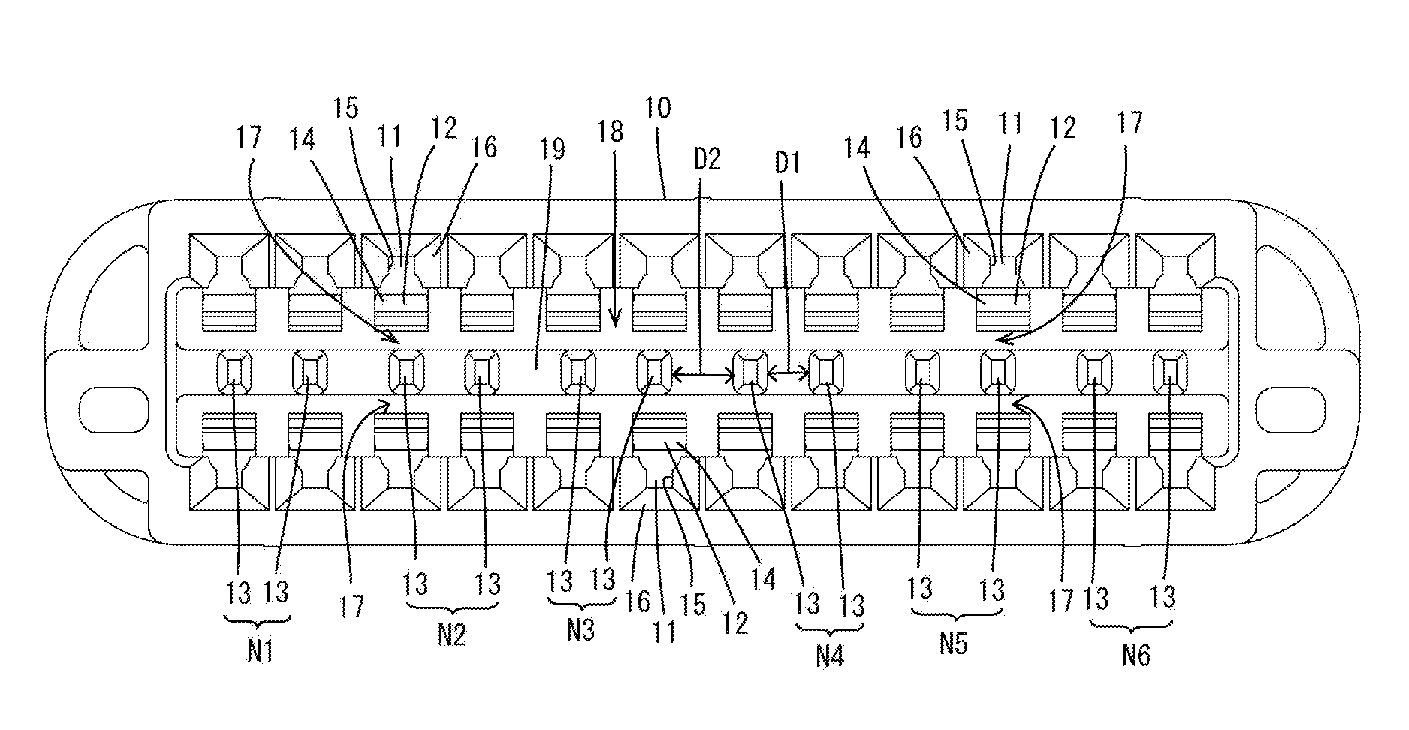
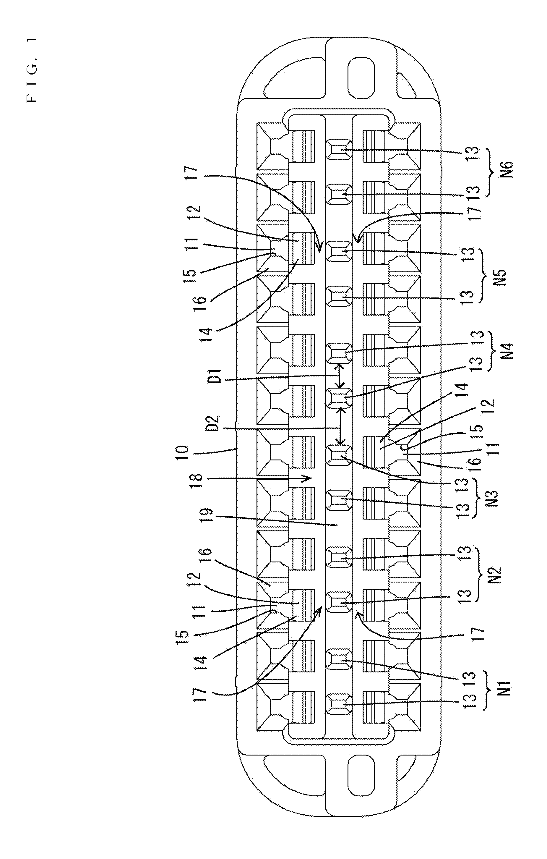
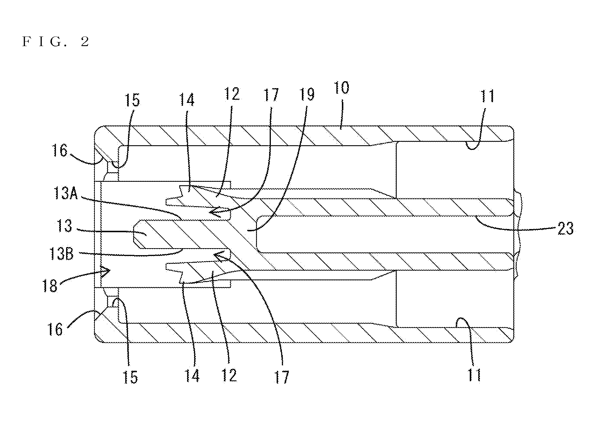
[0019]A connector according to an embodiment of the invention is illustrated in FIGS. 1-6 and includes a housing 10 that is made of synthetic resin and is connectable to an unillustrated mating housing. Terminal fittings 60 made of electrically conductive metal are to be mounted into the housing 10. An inspection tool 70 is mounted into the housing 10, as shown in FIG. 4, to determine whether or not an inserted state of the terminal fittings 60 is proper. In the following description, a front-back direction of the connector is defined so that a front of the terminal fittings 60 in an inserting direction into the housing 10 is a front end and a front-back direction of the inspection tool 70 is defined so that an end facing the front of the housing 10 at an initial position is a front end. Further, a vertical direction is based on each figure except FIG. 3. Furthermore, a width direction is a direction perpendicular to the front-back direction and the vertical direction and synonymous...


PUM


Abstract

Locking lances (12) for retaining and locking terminal fittings (60) are deflectably provided at inner walls of cavities (11) of a housing (10). The housing (10) includes excessive deflection regulating pieces (13) each provided at a position facing the locking lance (12) in a deflecting direction of the locking lance (12) and configured to regulate excessive deflection of the locking lance (12). Locking lances (12) are provided side by side in a width direction perpendicular to an inserting direction of the terminal fittings (60). A plurality of the excessive deflection regulating pieces (13) are provided side by side in the width direction at positions corresponding to the locking lances (12) and have also a function of positioning an inspection tool (70) for inspecting an inserted state of the terminal fittings (60).

Description

BACKGROUND[0001]1. Field of the Invention[0002]The invention relates to a connector and an inspection tool therefor.[0003]2. Description of the Related Art[0004]U.S. Pat. No. 6,302,735 discloses a connector with a housing that has cavities, and a deflectable locking lance projects forward at an inner wall of each cavity. A terminal fitting is inserted into each cavity from behind, and the properly inserted terminal fitting is retained and locked by the locking lance.[0005]The cavities and the locking lances are provided side by side in a width direction that is perpendicular to an inserting direction of the terminal fittings into each cavity. A detection piece of a retainer is inserted into a deflection space for each locking lance in the housing and is provided with an excessive deflection regulating portion. If the terminal fitting is left incompletely inserted, a tip part of the locking lance contacts the excessive deflection preventing portion when the retainer is inserted. In t...

Claims


Application Information

Patent Timeline
Patent Type & Authority Applications(United States)
IPC IPC(8): H01R13/422H01R43/20
CPCH01R43/20H01R13/4223
Inventor CHONAN, TAKAHISANAKAI, KAZUO
Owner SUMITOMO WIRING SYST LTD
Why Eureka
Try Eureka