
Combine Header with Support Wheels

a technology of support wheels and combine headers, applied in the field of combine headers, can solve the problems of difficult to combine such a combine header with automatic height control, the support wheels themselves are unsuitable for guiding the combine header, and the solution appears to be very complex

Active Publication Date: 2015-12-31
CARL GERINGHOFF GMBH & CO KG
View PDF32 Cites 5 Cited by
  • Summary
  • Abstract
  • Description
  • Claims
  • Application Information

AI Technical Summary

Benefits of technology

This patent describes a way to adjust the height of a combine header when driving across a field with a harvesting machine. By using support wheels on the header, the machine can automatically adjust the height as the ground goes up or down. This eliminates the need for active adjustments during forward travel and prevents ground contact with the cutter bar. The technical effect is a simplified and efficient way to adapt the combine header to the ground conditions, improving the performance of the harvesting machine.

Problems solved by technology

The support wheels themselves are unsuitable for guiding the combine header close to the ground because they are arranged at a significant spacing away from the cutter bar that is decisive for the cutting function of the combine header.
Such a solution appears to be very complex.
In particular, it appears to be difficult to combine such a combine header with automatic height control of different combine models of different manufacturers so as to provide proper functionality because they are each provided with different control algorithms with different control strategies, control rates, and control parameters.

Method used


Image

  • Combine Header with Support Wheels
  • Combine Header with Support Wheels
  • Combine Header with Support Wheels

Examples


Embodiment Construction

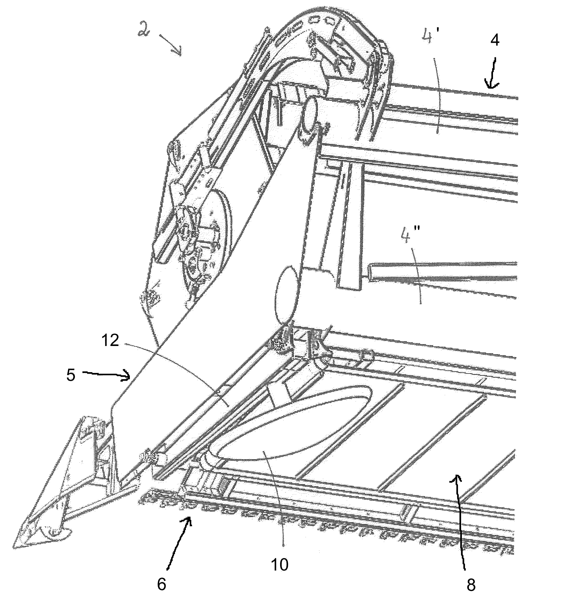
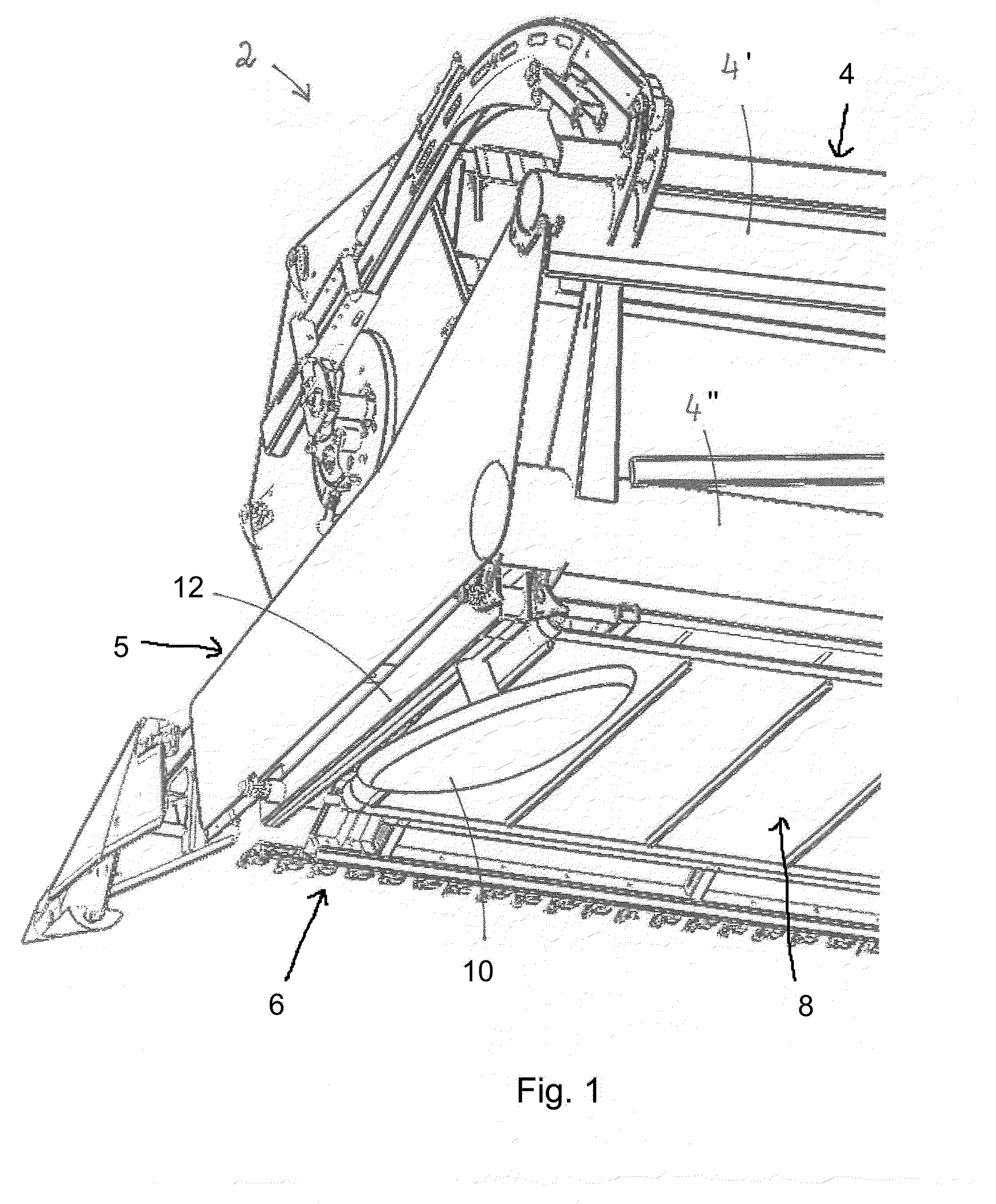
[0028]In FIG. 1, the combine header 2 is shown in a view at a slant from below. In this view, the frame 4 can be seen which in the embodiment comprises two transverse beams 4′, 4″ from which the sidewall 5 is extending forwardly. Between the transverse beams 4′, 4″ of the frame 4 and the cutter bar 6 attached to the leading end of the combine header 2, there is a conveying device 8. The conveying device 8 in the embodiment is a draper conveying device. In deviation therefrom, other conveying devices such as conveyor screws can be used also.

[0029]Below the sidewall 5 at the lateral end of the combine header 2, the frame 4 comprises a bar 12 fixedly connected to elements of the frame 4. The support wheel 10 is attached to the bar 12.

[0030]The support wheel 10 is located underneath the combine header 2. As can be seen in the rear view of the combine header 2 in FIG. 2, the support wheel 10 is projecting only slightly past the sidewall 5 of the combine header 2. The larger part of the s...


PUM


Abstract

A combine header for a harvesting machine is provided with a frame and a cutter bar connected to a leading end of the frame. A conveying device connected to the frame conveys stalk material cut by the cutter bar. A drive device drives the cutter bar and the conveying device. First support wheels are connected to the frame at lateral ends of the combine header and support the combine header on the ground. The support wheels arranged underneath the combine header.

Description

BACKGROUND OF THE INVENTION [0001]The present invention concerns a combine header for a harvesting machine, comprising a frame, a cutter bar, a conveying device for cut stalk material, and drive devices for driving the cutter bar and the conveying device, and support wheels attached to the outer sides of the combine header for supporting the combine header on the ground.[0002]A combine header of the aforementioned kind is disclosed in U.S. Pat. No. 8,245,489. The combine header is connected by means of an adapter frame to the feed channel of a combine harvester. The feed channel is height-adjustable and the combine header is additionally pivotable and height-adjustable by means of the adapter frame. In addition, the combine header is also supported by support wheels on the ground wherein the support wheels are arranged at a spacing behind the combine header and are height-adjustable. As a result, in this solution three height-adjustable components must be joined with each other in a...

Claims


Application Information

Patent Timeline
Patent Type & Authority Applications(United States)
IPC IPC(8): A01D41/14A01D34/00
CPCA01D41/14A01D75/00
Inventor SCHULZE SELTING, STEPHANWEBERMANN, DIRKALBINGER, BERNDTIESSEN, REIMER
Owner CARL GERINGHOFF GMBH & CO KG
Learn More