Eureka AIR delivers breakthrough ideas for toughest innovation challenges, trusted by R&D personnel around the world.

Scalpel handle having a blade shield utilizing over center spring

Active Publication Date: 2015-07-09
BOSELA DESIGN
View PDF19 Cites 9 Cited by
  • Summary
  • Abstract
  • Description
  • Claims
  • Application Information

AI Technical Summary

Benefits of technology

The invention is a scalpel handle that can hold a blade and has a blade shield to cover the cutting edge when not in use. The blade shield can be moved from covering the blade to exposing it for use by a manual actuator mechanism. The handle also has an over center spring that helps move the blade shield back to its original position when the actuator mechanism is moved. The technical effect of this invention is to provide a scalpel handle that can easily and quickly switch between covering and exposing the blade, making it easier to use and control during surgical procedures.

Problems solved by technology

A limitation associated with shielded scalpel designs of the prior art relates to the schemes by which the blade shields are held in place in each of its blade-covering position and its out-of-the-way position.
In other words, if the fit-up between adjacent components of the scalpel design is too loose (resulting, for example, from tolerance error during manufacture of the scalpel components), the blade shield is not likely to be firmly held in its blade-covering position when the actuator mechanism is moved into its first condition and also be firmly held in its blade-covering condition when the actuator mechanism is moved to its second condition.

Method used


Image

  • Scalpel handle having a blade shield utilizing over center spring
  • Scalpel handle having a blade shield utilizing over center spring
  • Scalpel handle having a blade shield utilizing over center spring

Examples


Embodiment Construction

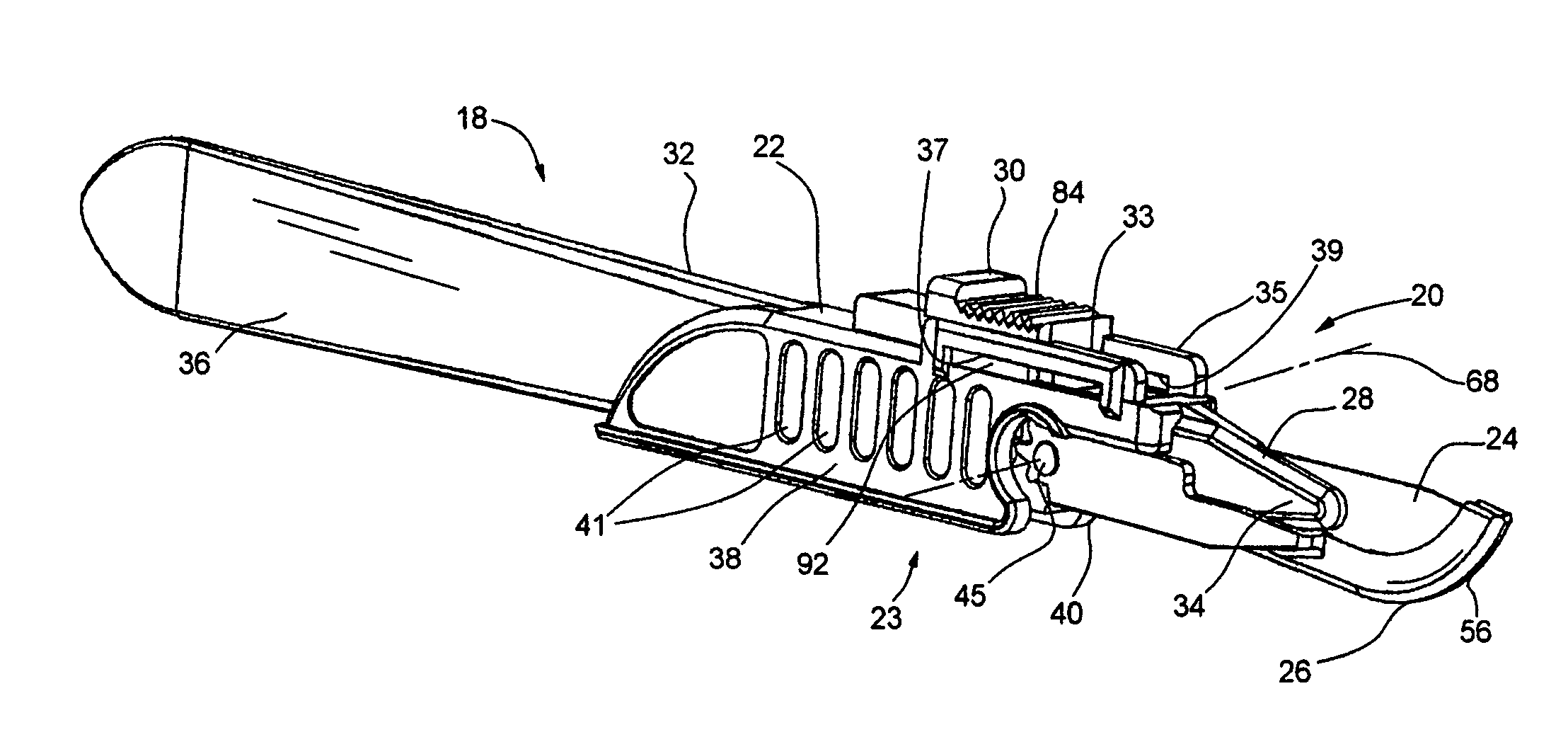
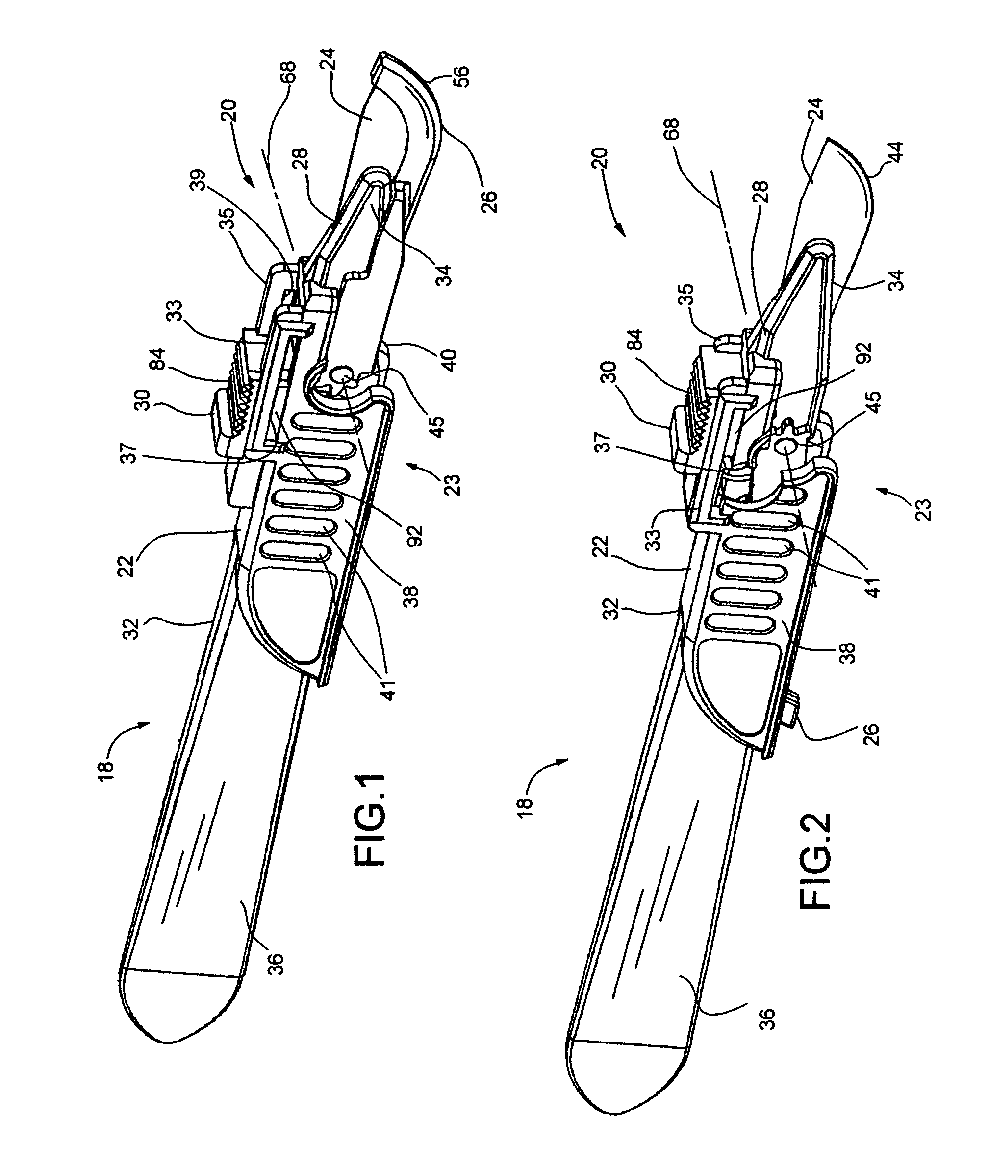
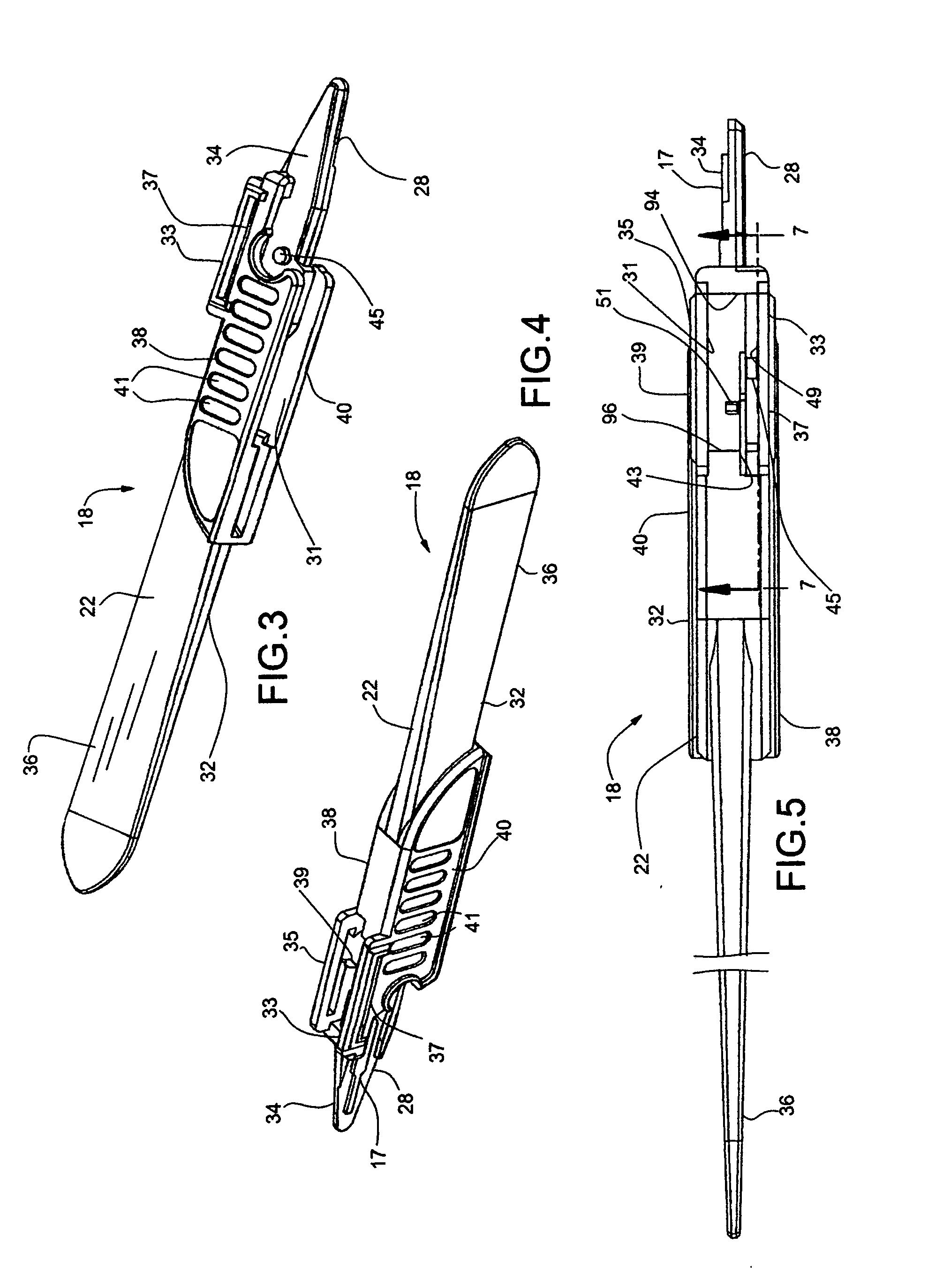
[0032]Turning now to the drawings in greater detail and considering first FIGS. 1 and 2, there is illustrated an embodiment, generally indicated 20, of a scalpel, or scalpel assembly, within which features of the present invention are embodied. Briefly, the scalpel 20 includes means, generally indicated 18, providing a handle of the scalpel 20 and an elongated blade 24 which is connected to the handle-providing means 18. The handle-providing means 18 of the depicted scalpel 20 includes an elongated handle member 22 to which the elongated blade 24 is fixedly secured adjacent one (i.e. a forward) end of the handle member 22 and further includes a blade shield 26 which is joined to the handle member 22 for pivotal movement of the shield 26 relative to the handle member 22 between a first condition, or position, as illustrated in FIG. 1, at which the shield 26 covers, and thereby protects, the cutting edge of the blade 24 and a second condition, or position, as illustrated in FIG. 2, at...


PUM


Abstract

A scalpel handle for holding a blade includes a handle member and a blade shield for covering the cutting edge of the blade. The blade shield is connected to the handle member for movement relative thereto between a blade-covering position and an out-of-the-way position, and a finger-operable actuator is mounted upon the handle member for movement relative thereto and is connected to the shield so that by moving the actuator between first and second conditions, the shield is moved between its blade-covering and its out-of-the-way positions. An over center spring is interposed between the actuator and the handle member so that upon movement of the actuator into its second condition, the shield is biased into the out-of-the-way position and so that upon movement of the actuator into its first condition, the shield is biased into the blade-covering position.

Description

[0001]This invention is a continuation-in-part of application Ser. No. 13 / 998,559, filed Nov. 8, 2013 and entitled SCALPEL HANDLE HAVING A BLADE SHIELD, the disclosure of which is incorporated herein by reference.BACKGROUND OF THE INVENTION[0002]This invention relates generally to surgical scalpels and relates, more particularly, to means and methods by which the cutting edge of a scalpel blade is covered between periods of use.[0003]It is known that in order to reduce the risk of inadvertent cuts from a scalpel in a surgical environment as, for example, the scalpel is passed from one individual to another, the cutting blade of the scalpel can be covered with a safety shield between periods of use, and it is this class of shielded scalpels to which the present invention is to be compared. One such shielded scalpel is described in my co-pending U.S. Ser. No. 13 / 998,559 as having an elongated handle, a cutting blade which extends from the handle and a safety shield which is attached t...

Claims


Application Information

Patent Timeline
IPC IPC(8): A61B17/3211
CPCA61B2017/32113A61B17/3211B26B29/02A61B17/3213
Inventor VODINH, HIEN
Owner BOSELA DESIGN
Why Eureka
Eureka Blog
Learn More