
Four-channel display power reduction with desaturation

a technology of desaturation and display power, applied in the field of image processing techniques, can solve the problems of inorganic led not providing as much power savings, and it is difficult to increase these values significantly

Active Publication Date: 2015-06-25
GLOBAL OLED TECH
View PDF9 Cites 3 Cited by
  • Summary
  • Abstract
  • Description
  • Claims
  • Application Information

AI Technical Summary

Benefits of technology

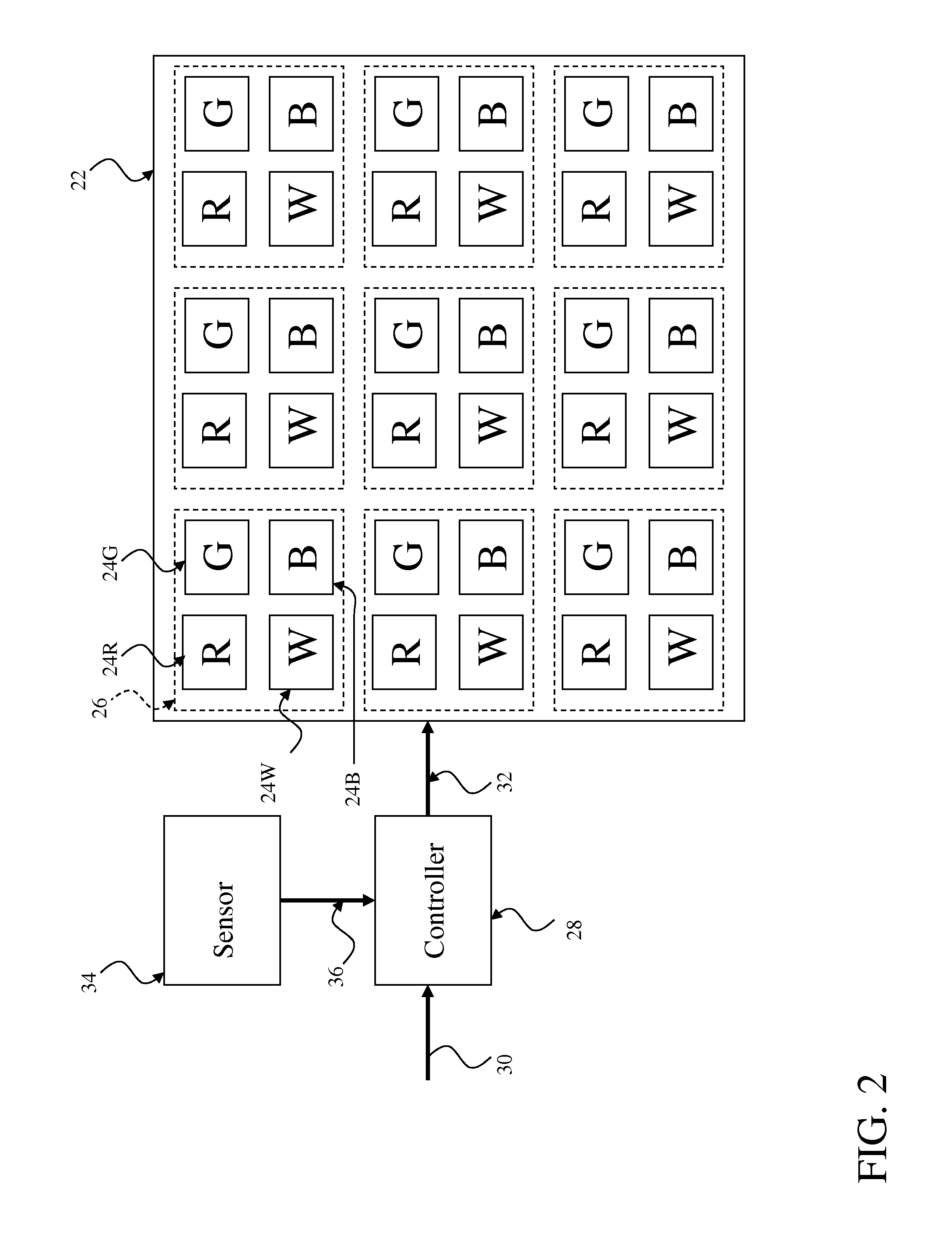
The patent describes a method for creating a display with four different colored subpixels. These subpixels can emit light in response to a modulated signal, such as a voltage or current. The display can be made using an electroluminescent display, such as an OLED display, which has red, green, blue, and white subpixels that produce light in proportion to the current passed through each subpixel. The method includes forming an active matrix layer with active matrix circuitry for providing a current to each subpixel, and patterning a color filter layer with red, green, blue, and optionally clear filters to produce the desired color of light. The light is then directed through the color filters to produce the desired color, with the filters absorbing undesired spectral components of the light and reducing its luminous efficiency. The technical effect of this method is a more efficient and accurate display of colors.

Problems solved by technology

Since the display is not capable of producing panel intensity values over unity, it is not possible to increase these values significantly without requiring larger panel intensity values than can be physically realized by the display.
Therefore, this inorganic LED will typically not provide as much power savings as is provided in a true emissive display in which the level of luminance that is produced by each subpixel can be individually modulated.

Method used


Image

  • Four-channel display power reduction with desaturation
  • Four-channel display power reduction with desaturation
  • Four-channel display power reduction with desaturation

Examples


Embodiment Construction

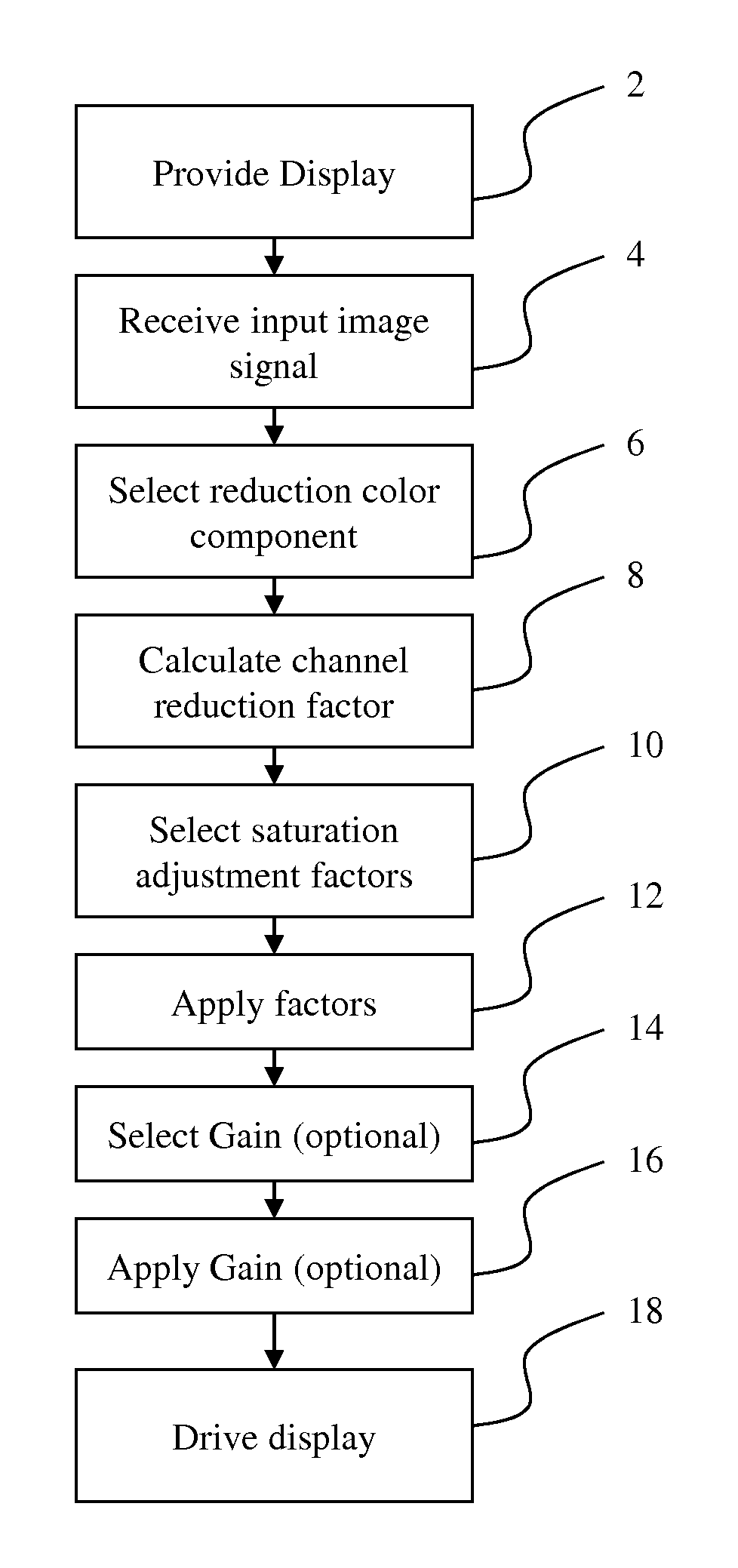
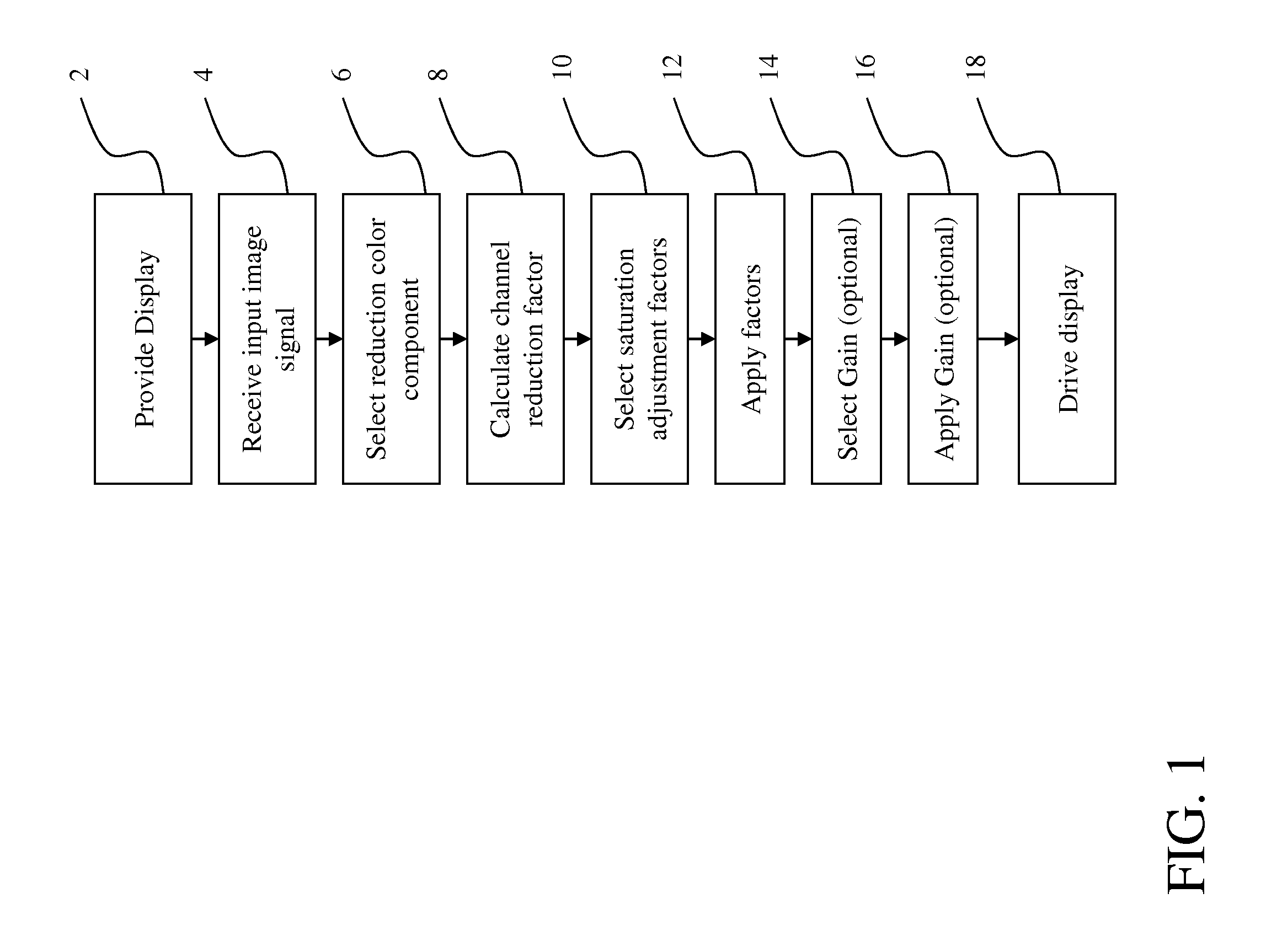
[0028]A method is provided for presenting an image on a display having color channel dependent light emission to reduce the power consumption of the display. This method includes the steps shown in FIG. 1. As shown an image input signal is received 2. This image input signal includes a plurality of input pixel signals, each input pixel signal having three color components. A reduction color component is selected 4 for reduction. A reduction factor is calculated 6 for each input pixel signal dependent upon a distance metric between the input pixel signal and the selected reduction color component. A respective saturation adjustment factor is selected 8 for each color component of each pixel signal. An image output signal is produced 10 having four color components from the image input signal using the reduction factors and saturation adjustment factors to adjust the luminance and color saturation, respectively, of the image input signal. A four-channel emissive display device is prov...


PUM


Abstract

A method of presenting an image on a display device having color channel dependent light emission comprising receiving an image input signal including a plurality of three-component input pixel signals; selecting a reduction color component; calculating a reduction factor for each input pixel signal dependent upon a distance metric between the input pixel signal and the selected reduction color component; selecting a respective saturation adjustment factor for each color component of each pixel signal; producing an image output signal having four color components from the image input signal using the reduction factors and saturation adjustment factors to adjust the luminance and color saturation, respectively, of the image input signal; providing a four-channel display device having color channel dependent light emission; and applying the image output signal to the display device to cause it to present an image corresponding to the image output signal.

Description

CROSS REFERENCE TO RELATED APPLICATIONS[0001]This patent is a continuation of commonly assigned, co-pending U.S. patent application Ser. No. 12 / 397,500, filed Mar. 4, 2009, titled “Four-Channel Display Power Reduction With Desaturation” by Miller et al., since published as U.S. 2010-0225673 A1.[0002]Reference is also made to commonly assigned U.S. patent application Ser. No. 12 / 172,440, filed Jul. 14, 2008, titled “Method For Improving Display Lifetime” by Miller, since issued as U.S. Pat. No. 8,237,642, and commonly assigned U.S. patent application Ser. No. 12 / 174,085, filed Jul. 16, 2008, titled “Converting Three-Component To Four-Component Image” by Cok et al., since issued as U.S. Pat. No. 8,169,389, the disclosures of which are incorporated herein.FIELD OF THE INVENTION[0003]The present invention relates to image processing techniques for presenting images on displays having color channel dependent light emission, and more particularly, to methods, apparatuses, and systems for ...

Claims


Application Information

Patent Timeline
Patent Type & Authority Applications(United States)
IPC IPC(8): G09G5/02G09G5/10
CPCG09G5/02G09G2330/021G09G5/10G09G3/2003G09G3/3208G09G2300/0452G09G2320/041G09G2320/0626G09G2320/0666G09G2360/144G09G3/20G09G3/3413G09G3/3607G09G5/04G09G2320/0233G09G2320/0271G09G2320/0613
Inventor MILLER, MICHAEL E.WHITE, CHRISTOPHER J.
Owner GLOBAL OLED TECH
Learn More